
Eureka
For R&D, Eureka makes reading and utilizing patents & technical documents easy.
Eureka AIR
Designed for self-driven R&D workflows. Generate viable solutions, solve complex R&D challenges, empower your innovation with AI.

Eureka Materials
Designed for material experts only. Revolutionize your material R&D, from search, analyze, to developing new materials.

TechResearch
Generate reliable direction feasibility study reports for your R&D in just a few steps.

TechSeek
Discover and master advanced knowledge NOW. Basics, ideas, possibilities, all at once.

TechMind
As an expert in R&D Theories, TechMind can generates customized viable solutions instantly.

TechRisk
Analyze your overall solution with one click, know your potential R&D risks in advance.

TechMonitor
Get weekly tech updates, stay abreast of the latest tech innovations and key insights.
Fingerprint image frame sequence combination method based on wave form match
A fingerprint image and image frame technology, applied in the field of image processing process control
- Summary
- Abstract
- Description
- Claims
- Application Information
AI Technical Summary
Problems solved by technology
Method used
Image

Examples
Embodiment 1
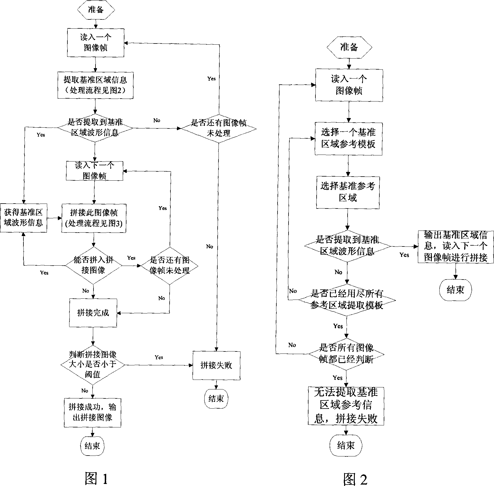
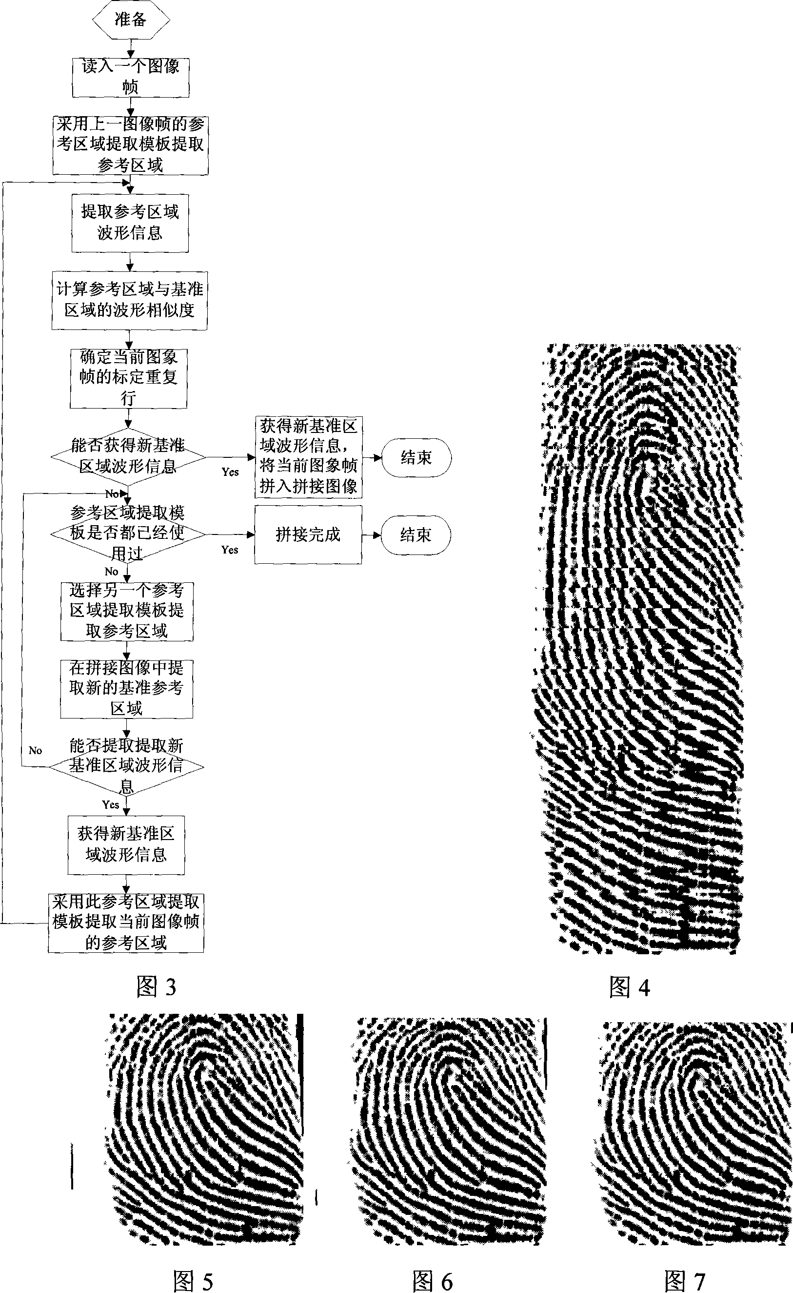
[0048] The image splicing process in this embodiment will be described in detail below in conjunction with FIGS. 1 , 2 , and 3 .
[0049] First of all, it is assumed that the image size of each frame is 16 rows, 192 columns, and the gray level is 0-255. The maximum size of the image after normal splicing is 192 rows, 192 columns. A total of 3 reference area extraction templates are used, which extract the 65th to 128th columns, the 1st to 64th columns and the 129th to 192nd columns in the 1st to 14th rows of the reduced image frame respectively.
[0050] After receiving the first image frame, it is reduced, and the remaining part is stitched into the bottom of the stitched image. Select a reference area extraction template to extract the benchmark reference area, and calculate the binarized gray threshold as the average gray value of the reference area minus 16. Binarize the benchmark reference area according to this threshold, convert each image line into a binary sequence, ...
Embodiment 2
[0056] The image splicing process in this embodiment will be described in detail below in conjunction with FIGS. 1 , 2 , and 3 .
[0057] First of all, it is assumed that the image size of each frame is 16 rows, 192 columns, and the gray level is 0-255. The maximum size of the image after normal splicing is 192 rows, 192 columns. A total of 3 reference area extraction templates are used, which extract the 73rd to 120th columns, the 25th to 72nd columns and the 121st to 168th columns in the 1st to 14th rows of the reduced image frame respectively.
[0058] After receiving the first image frame, it is reduced, and the remaining part is stitched into the bottom of the stitched image. Select a reference area extraction template to extract the benchmark reference area, and calculate the binarized gray threshold as the average gray value of the reference area minus 16. Binarize the benchmark reference area according to this threshold, convert each image line into a binary sequence,...
Embodiment 3
[0064] The image splicing process in this embodiment will be described in detail below in conjunction with FIGS. 1 , 2 , and 3 .
[0065] First of all, it is assumed that the image size of each frame is 16 rows, 192 columns, and the gray level is 0-255. The maximum size of the image after normal splicing is 192 rows, 192 columns. A total of 3 reference area extraction templates are used to extract the 81st to 112th columns, the 49th to 80th columns and the 113th to 144th columns in the 1st to 14th rows of the reduced image frame respectively.
[0066] After receiving the first image frame, it is reduced, and the remaining part is stitched into the bottom of the stitched image. Select a reference area extraction template to extract the benchmark reference area, and calculate the binarized gray threshold as the average gray value of the reference area minus 16. Binarize the benchmark reference area according to this threshold, convert each image line into a binary sequence, and...
PUM
 Abstract
Description
Claims
Application Information
 - R&D Engineer
- R&D Manager
- IP Professional
- Industry Leading Data Capabilities
- Powerful AI technology
- Patent DNA Extraction
Browse by: Latest US Patents, China's latest patents, Technical Efficacy Thesaurus, Application Domain, Technology Topic, Popular Technical Reports.
© 2024 PatSnap. All rights reserved.Legal|Privacy policy|Modern Slavery Act Transparency Statement|Sitemap|About US| Contact US: help@patsnap.com