Color filter substrate, LCD device and color display device using the same

A color filter and substrate technology, applied in nonlinear optics, instruments, optics, etc., can solve problems such as display quality degradation

Inactive Publication Date: 2007-12-19
DAWNCREST IP LLC
View PDF0 Cites 3 Cited by
  • Summary
  • Abstract
  • Description
  • Claims
  • Application Information

AI Technical Summary

Problems solved by technology

Therefore, if the additive color mixing is not performed in the unit pixel, the display quality will be degraded.
[0009] In addition, if the arrangement or shape of the colored parts as in Patent Document 1 is used, the color mixing property is improved. However, in a passive matrix type display device in which the transparent electrode needs to be formed in almost the same shape as the colored layer, the transparent electrode cannot be formed in such a shape. The application electrode

Method used


Image

  • Color filter substrate, LCD device and color display device using the same
  • Color filter substrate, LCD device and color display device using the same
  • Color filter substrate, LCD device and color display device using the same

Examples


Embodiment 1

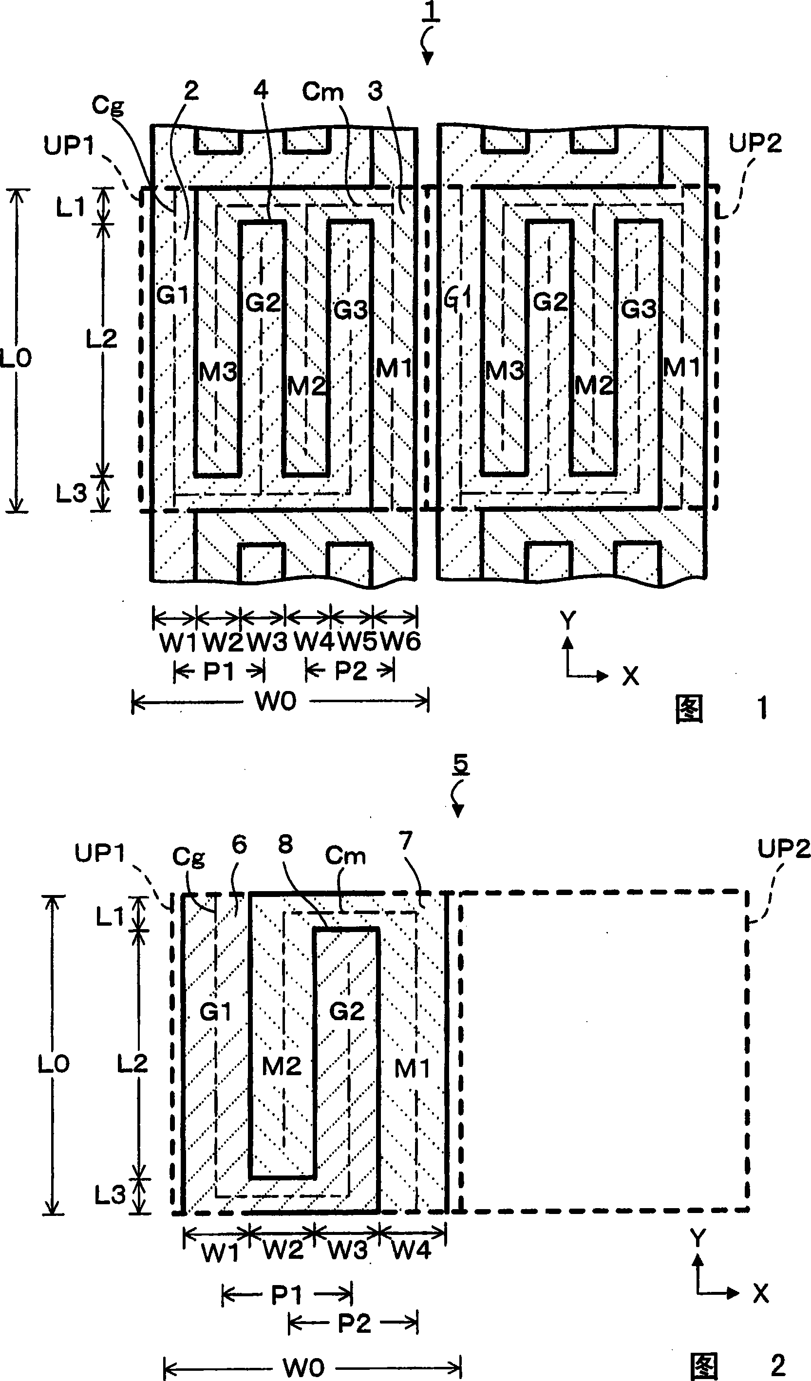
[0043]The shape and arrangement of the color filter substrate and the colored layer of the display device according to this embodiment will be described using the plan view of FIG. 1 . As shown in the figure, the unit pixel UP1 and the same unit pixel UP2 as the unit pixel UP1 are arranged side by side. The unit pixel UP1 has a rectangular shape with a length of 200 μm (L0) and a width of 222 μm (W0). A plurality of unit pixels UP1 are arranged in the X direction and the Y direction to form a matrix. The unit pixel UP1 has a first color sub-pixel 2 and a second color sub-pixel 3 with different colors. For example, the first-color sub-pixel 2 is a green colored layer or light-emitting portion, and the second-color sub-pixel 3 is a magenta colored layer or light-emitting portion. In addition, each sub-pixel has a continuous single plane area, and the first-color sub-pixel 2 and the second-color sub-pixel 3 are separated by a boundary 4 . The border area 4 is a black color fil...

Embodiment 2

[0053] FIG. 2 schematically shows the state of the two-color color filter substrate (color layout 5 of the colored layer) of the present embodiment when viewed in plan. As shown in the figure, the first color sub-pixel 6 and the second color sub-pixel 7 having different colors are formed in the unit pixel UP1. The sub-pixel 6 of the first color and the sub-pixel 7 of the second color are divided by the boundary area 8 . The unit pixel UP1 has a rectangular shape with a length L0 and a width W0, and has a 40000 μm 2 above the area. The sub-pixels 6 of the first color and the sub-pixels 7 of the second color respectively have a single continuous plane area. The first color sub-pixel has a region G1 with a length of L0 and a width of W1 and a region G2 with a length of L2 and a width of W3. Similarly, the second color sub-pixel 7 has a region M1 with a length L0 and a width W4 and a region M2 with a length L2 and a width W2. Here, W1 to W4 each have the same length and are no...

Embodiment 3

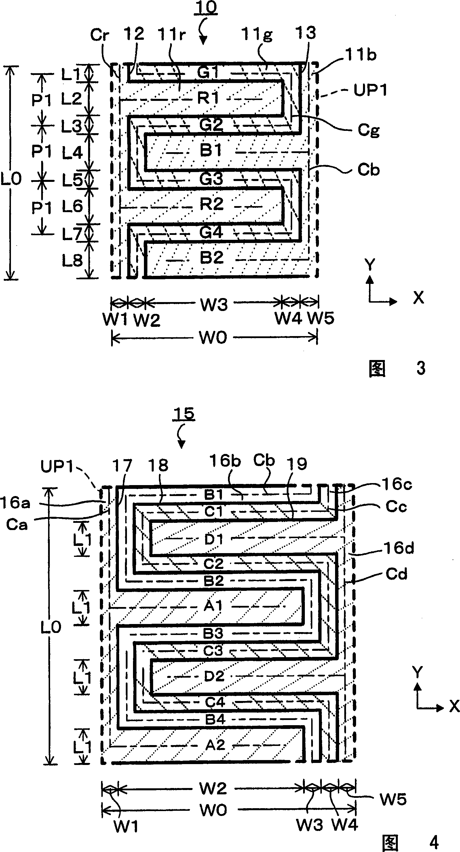
[0059] FIG. 3 is a plan view schematically showing the color filter substrate (color layout 10 of colored layers) of this embodiment. As shown in the figure, the unit pixel UP1 has three sub-pixels: a red first sub-pixel 11r, a green second sub-pixel 11g, and a blue third sub-pixel 11b. The unit pixel UP1 is a square whose length L0 and width W0 are respectively 300 μm, and its area (L0×W0) is 90000 μm 2, arranged in the X direction and the Y direction to form a matrix. In addition, the second sub-pixel 11g is arranged between the first sub-pixel 11r and the third sub-pixel 11b. The first sub-pixel 11r and the second sub-pixel 11g are divided by the boundary area 12 , and the second sub-pixel 11g and the third sub-pixel 11b are divided by the boundary area 13 .

[0060] The first sub-pixel 11r has a region R1 with a width of 50 μm (L2) and a length of 225 μm (W2+W3) and a region R2 with a width of 50 μm (L6) and a length of 225 μm (W2+W3). Therefore, the width of each regio...


PUM

PropertyMeasurementUnit
areaaaaaaaaaaa
areaaaaaaaaaaa
areaaaaaaaaaaa

Abstract

In a color filter substrate in which a unit pixel is composed of a plurality of sub-pixels of different colors and arranged two-dimensionally in a matrix, if the area of ​​the unit pixel exceeds 40,000 square microns, the sub-pixels constituting the color can be seen, The display quality is degraded. A plurality of sub-pixels with different colors constitute a unit pixel, the area of ​​a unit pixel is more than 40,000 square microns, and the sub-pixels have a periodic shape with a line width of no more than 100 microns. Periodically shaped regions of one sub-pixel are arranged so as to engage with each other, so that an observer can recognize a display after additive color mixing.

Description

technical field [0001] The present invention relates to color layout when performing color display. In particular, it relates to a color layout of a display device using a color filter substrate and a liquid crystal display device using the color filter substrate or a light-emitting element such as an EL element. Background technique [0002] As a display device capable of color display, a display device using a non-self-luminous liquid crystal display element, a self-luminous PDP element, or an EL element is put into practical use. These color display devices use, for example, red (R), green (G), and blue (B) sub-pixels as unit pixels, and perform color display by additive color mixing. In order to enable additive color mixing, the area of ​​the unit pixel composed of RGB is made as small as possible so that the observer cannot recognize each sub-pixel separately. In addition, a technique is known in which colored portions are arranged obliquely or in a triangular arrange...

Claims


Application Information

Patent Timeline
Patent Type & Authority Applications(China)
IPC IPC(8): G02F1/1335
Inventor 福地高和松田俊介
Owner DAWNCREST IP LLC
Why Eureka
Try Eureka