Image forming device and image forming method
An imaging device and imaging technology, which are applied to equipment, electrographics, optics, etc. using electric charge patterns, can solve problems such as deformation of a cleaning blade 901, inability to completely scrape off toner, and reduced cleaning effect.
- Summary
- Abstract
- Description
- Claims
- Application Information
AI Technical Summary
Problems solved by technology
Method used
Image

Examples
no. 1 example
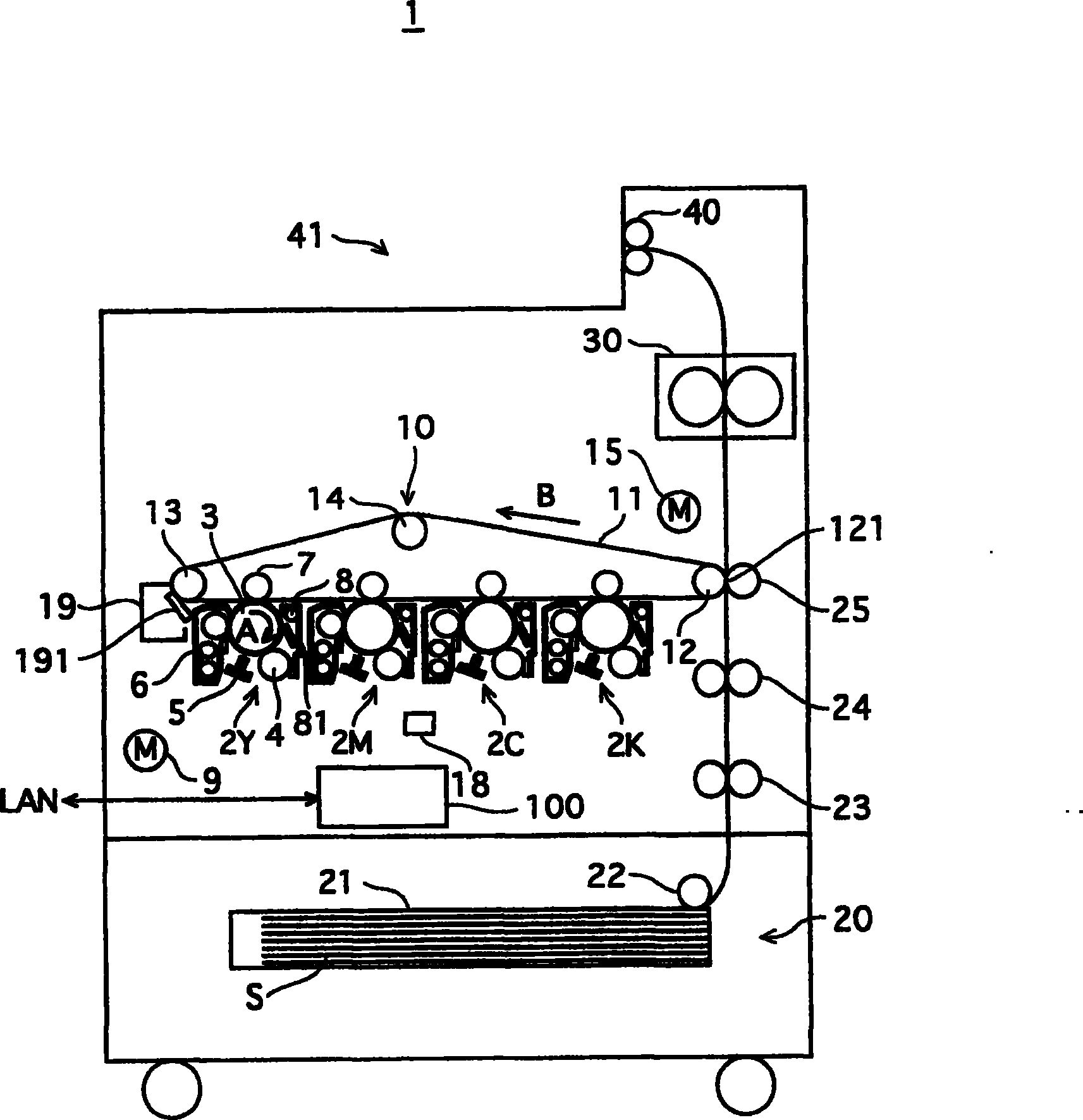
[0043] figure 1 The overall structure of the printer 1 in the first embodiment is shown. Such as figure 1 As shown, the printer 1 includes an image processing unit 10 , a feeding unit 20 , a fixing unit 30 , and a control unit 100 . Upon receiving an instruction to execute a print job from an external terminal device (not shown) through a network (in this example, a LAN) to which the printer 1 is connected, the printer 1 executes the print job according to the received instruction.
[0044] The image processing unit 10 includes image creation units 2Y, 2M, 2C, and 2K corresponding to yellow (Y), magenta (M), cyan (C), and black (K), respectively, a drum drive motor 9 , and an annular intermediate rotor. A printing belt 11 , a belt drive motor 15 , and a belt cleaning unit 19 .
[0045] The image creating unit 2Y includes a photosensitive drum 3 driven by a drum drive motor 9 along the figure 1Rotating in the direction indicated by the arrow A shown, the charging roller ...
no. 2 example
[0093] In the first embodiment, reverse rotation is controlled according to the magnitude of coverage. In a second embodiment, the reverse rotation will be controlled according to the internal temperature of the device. This is a difference from the first embodiment. In the following description of the second embodiment, description of what has already been explained in the first embodiment is omitted, and components common to both embodiments have the same reference numerals.
[0094] Figure 6 The contents of the reverse rotation information table 202 stored in the reverse rotation information storage unit 104 are shown. Figure 7 A specific example of the relationship between the impact resistance of the cleaning blade and the temperature is shown.
[0095] Such as Figure 6 As shown, the reverse rotation information table 202 shows the correspondence between the internal temperature of the device and the number of reverse rotations. Figure 6 The table shown indicates...
no. 3 example
[0104] The difference between this embodiment and the above-described embodiments is that the pressing force applied to the cleaning blade is variable.
[0105] Figure 9A and 9B The structure of the belt cleaning unit 301 in this embodiment is shown. Figure 9A shows the status of the cleaning blade and normal pressing force contact, while Figure 9B Shows the state of contact between the cleaning blade and the weak pressing force.
[0106] Such as Figure 9A and 9B As shown, the belt cleaning unit 301 includes a frame 311 , a cleaning blade 312 , a blade support member 313 , a tension spring 314 , a cam 315 and a cam driving motor 316 .
[0107] The frame 311 is secured to a base or the like of the device (not shown).
[0108] The cleaning blade 312 is attached to the blade supporting member 313 with its edge in contact with the surface of the intermediate transfer belt 11 .
[0109] The scraper support member 313 is supported so that it can Figure 9A and 9B In the...
PUM
 Abstract
Description
Claims
Application Information
 - R&D
- Intellectual Property
- Life Sciences
- Materials
- Tech Scout
- Unparalleled Data Quality
- Higher Quality Content
- 60% Fewer Hallucinations
Browse by: Latest US Patents, China's latest patents, Technical Efficacy Thesaurus, Application Domain, Technology Topic, Popular Technical Reports.
© 2025 PatSnap. All rights reserved.Legal|Privacy policy|Modern Slavery Act Transparency Statement|Sitemap|About US| Contact US: help@patsnap.com