Automatic tree correcting device

An automatic and arboreal technology, applied in gardening tools/equipment, gardening, agriculture, etc., can solve the problems of difficult correction, automatic loosening and falling of ropes, etc., to reduce the cost of manual management, prevent reverse bending, and prevent loosening and falling off Effect

Pending Publication Date: 2022-04-26
CHONGQING PUBLIC TRANSPORTATION CAREER ACADEMY
View PDF0 Cites 0 Cited by
  • Summary
  • Abstract
  • Description
  • Claims
  • Application Information

AI Technical Summary

Problems solved by technology

Some medium and large trees are difficult to correct by manpower, especially unable to overcome the elastic deformation after correction
[0003] The existing simple technology to straighten the trees is usually to tie the iron rods and the trees together to force the trees to straighten. This method is easy to damage the root system of the trees, and the iron rods are easy to loosen, resulting in poor tree straightening effects; no ground support is required The binding type forcibly correcting the trunk must be tied very firmly, but with the slow correction of the trunk, the binding rope will automatically loosen, or even fall off. If it is not re-bound in time, the purpose of correcting the trunk will not be achieved
[0004] The tree is fixed and corrected by using brackets to support the hoop. This method is difficult to reset and adjust the center of gravity of trees whose center of gravity has shifted. If the adjustment is forced, it is easy to damage the trunk and root system of the tree. It is planned to use a slow correction method for the displaced trees, but manual monitoring is required, otherwise it will be difficult to achieve the purpose of timely adjustment of the trunk

Method used


Image

  • Automatic tree correcting device
  • Automatic tree correcting device
  • Automatic tree correcting device

Examples


Embodiment Construction

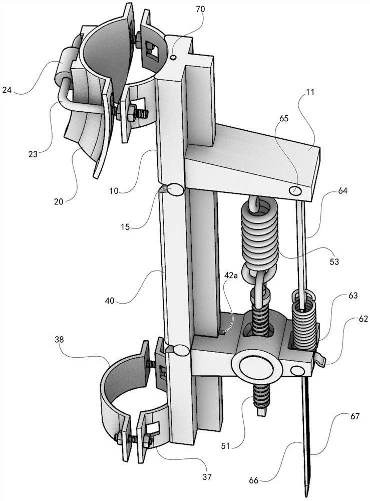
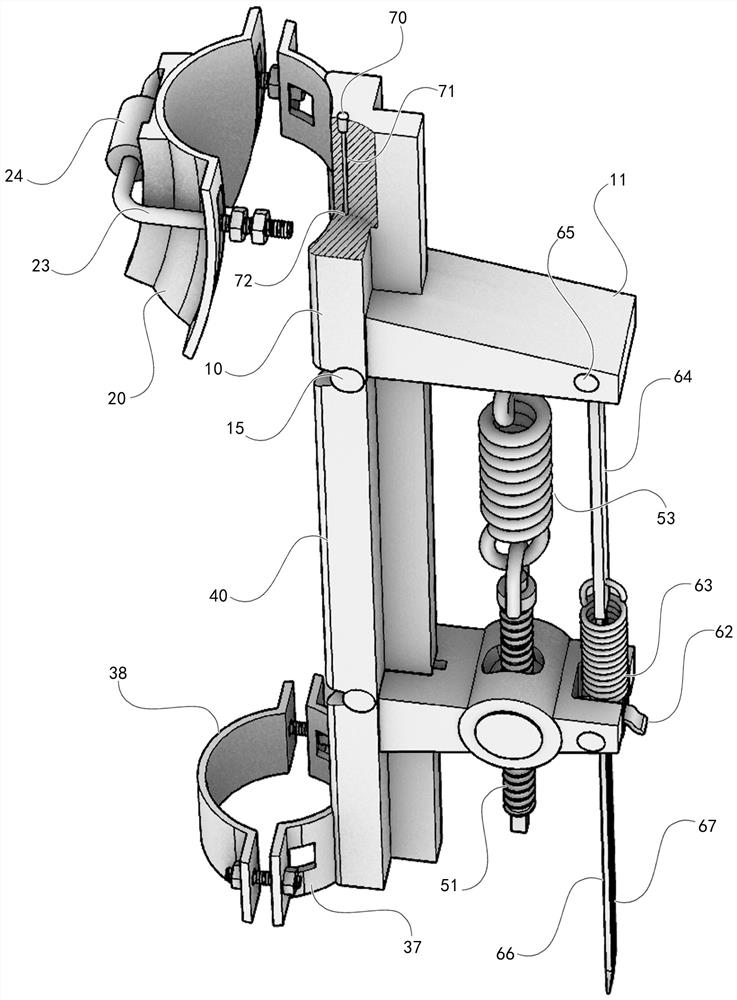
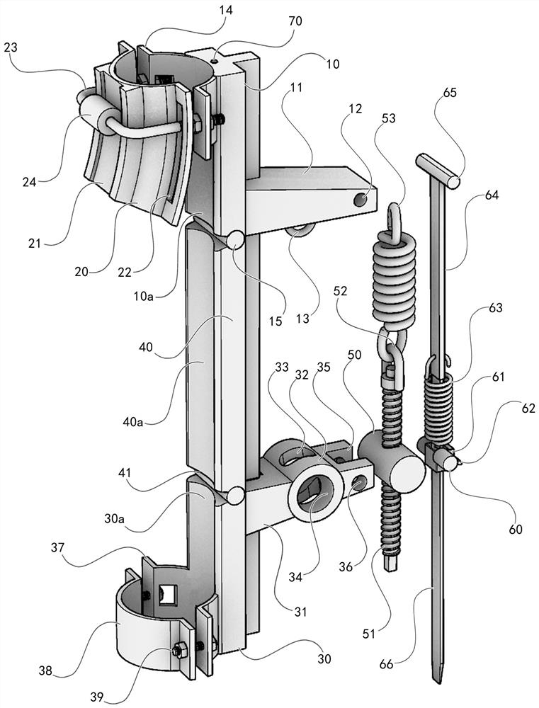
[0022] like Figure 1 to Figure 4 Shown, a kind of automatic straightening device for trees comprises a first fixed frame 10, a movable collar 20, a second fixed frame 30, an intermediate support 40, a second rotating shaft 50, a third rotating shaft 60, and a stop head 70; it is characterized in that , the first fixed frame 10 is provided with a first arc surface 10a, a first ferrule 14, a first fixed frame rotating shaft 15, a first limiting groove 43a and a first bracket 11, and the first bracket 11 is provided with a first A shaft hole 12 and annulus 13; a rolling groove 21 and a strip hole 22 are arranged on the movable ring 20; a bearing 24 is arranged in the middle of the U-bolt 23; a second arc surface 30a, a second Two limit grooves 42a, the third ferrule 37 and the second bracket 31; the top of the second bracket 31 is provided with a U-shaped groove 35, and the third shaft hole 36 runs through the U-shaped groove 35; the middle section of the second bracket 31 is pr...


PUM


Abstract

An automatic tree correcting device comprises a first fixing frame, a movable ferrule and a second fixing frame. The device is characterized in that the first fixing frame is provided with a first ferrule, a first fixing frame rotating shaft, a first limiting groove and a first support, and the first support is provided with a first rotating shaft hole and a circular ring; a rolling groove and a strip-shaped hole are formed in the movable ferrule; a bearing is arranged in the middle of the U-shaped bolt; the second fixing frame is provided with a second limiting groove, a third ferrule and a second support. A U-shaped groove is formed in the top end of the second bracket; the third rotating shaft hole penetrates through the U-shaped groove; a second rotating shaft hole is transversely formed in the middle of the second ferrule, and a threaded rod sliding groove is longitudinally formed in the middle of the second ferrule; the fixed ferrule and the third ferrule are fixed together through a straight bolt; the middle support is provided with a semicircular groove matched with the first fixing frame rotating shaft and a first limiting protrusion, and a middle support rotating shaft and a second limiting protrusion are arranged below the middle support. According to the invention, automatic and timely follow-up correction of the trunk can be realized.

Description

technical field [0001] The invention relates to the technical field of garden cultivation, in particular to an automatic tree straightening device. Background technique [0002] With the development of social economy, the process of urbanization has accelerated, and the scale of garden industry has continued to expand. During the cultivation and application of garden plants, the bending of the trunk affects the ornamental quality. Some medium and large trees are difficult to correct by manpower, especially the elastic deformation after correction. [0003] The existing simple technology to straighten the trees is usually to tie the iron rods and the trees together to force the trees to straighten. This method is easy to damage the root system of the trees, and the iron rods are easy to loosen, resulting in poor tree straightening effects; no ground support is required The binding type forcibly correcting the trunk must be tied very firmly, but as the trunk is slowly correc...

Claims


Application Information

Patent Timeline
Patent Type & Authority Applications(China)
IPC IPC(8): A01G17/14A01G7/06
CPCA01G17/14A01G7/06
Inventor 欧阳刚陈冬欧阳婧芸许余燕谭琬之葛圆
Owner CHONGQING PUBLIC TRANSPORTATION CAREER ACADEMY
Why Eureka
Try Eureka