
Method and apparatus for the elimination of interference fringes in an OLED device

A technology of light-emitting devices and organic light-emitting devices, which is applied in the direction of household components, electric solid-state devices, semiconductor devices, etc., and can solve the problems of reducing the airtightness and service life of devices, increasing the sealing surface area of ​​devices, reducing brightness and resolution, etc.

Inactive Publication Date: 2007-12-19
CORNING INC
View PDF1 Cites 13 Cited by
  • Summary
  • Abstract
  • Description
  • Claims
  • Application Information

AI Technical Summary

Problems solved by technology

The former will reduce the brightness and resolution, and the latter will increase the surface area of ​​the device seal, thereby reducing the airtightness and service life of the device

Method used


Image

  • Method and apparatus for the elimination of interference fringes in an OLED device
  • Method and apparatus for the elimination of interference fringes in an OLED device
  • Method and apparatus for the elimination of interference fringes in an OLED device

Examples


Embodiment Construction

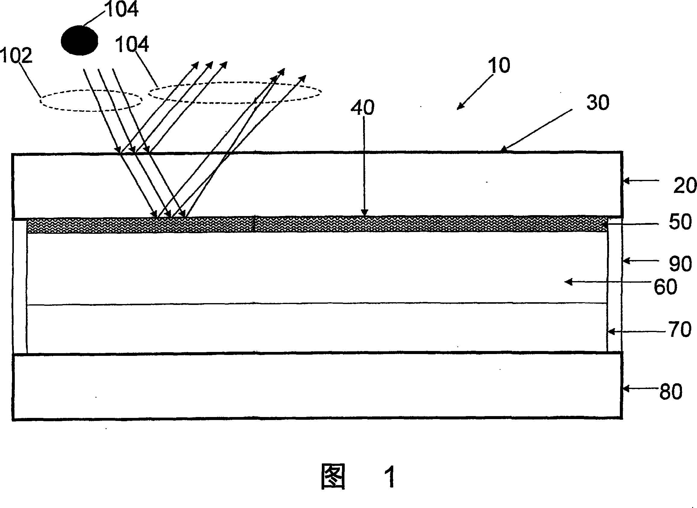
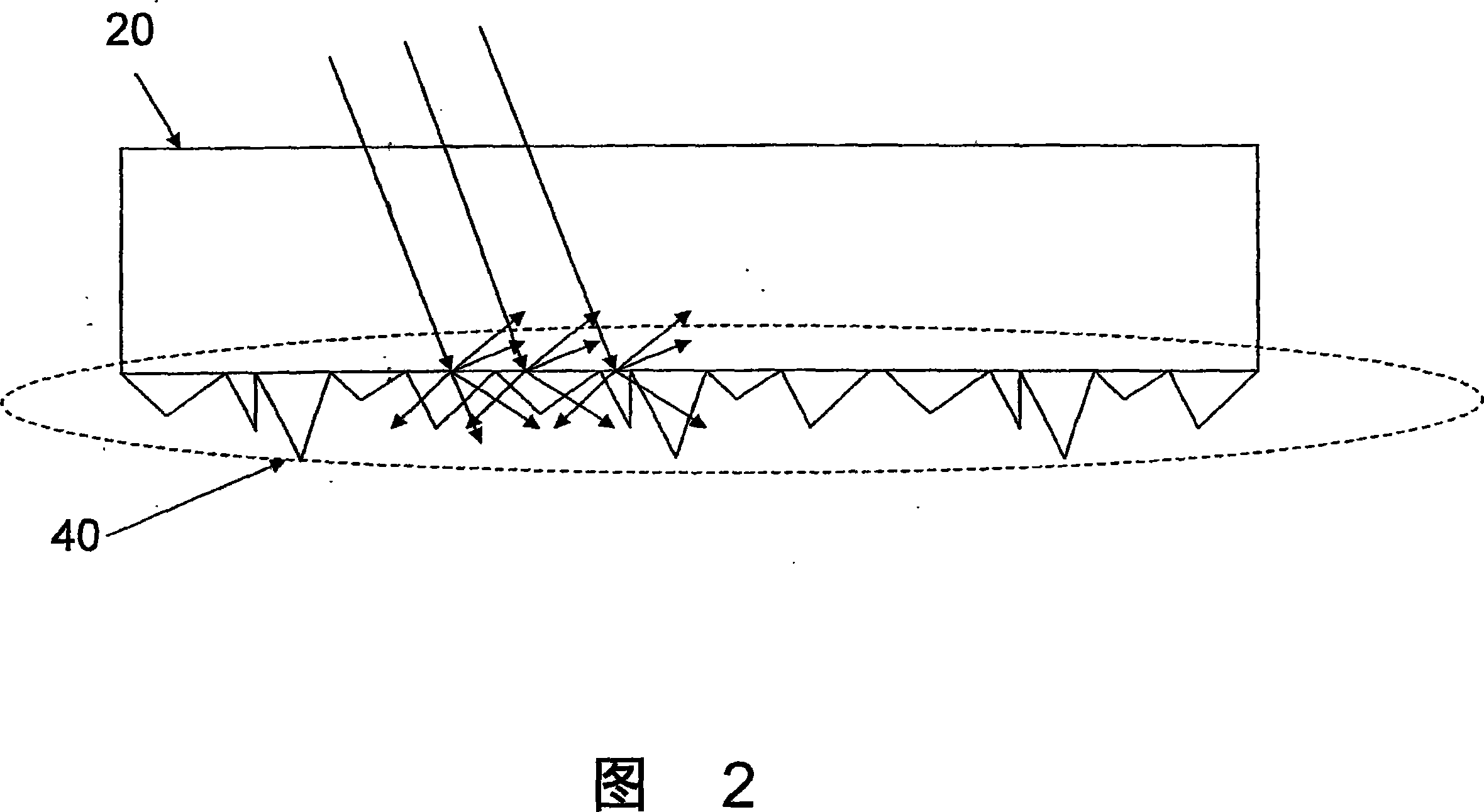
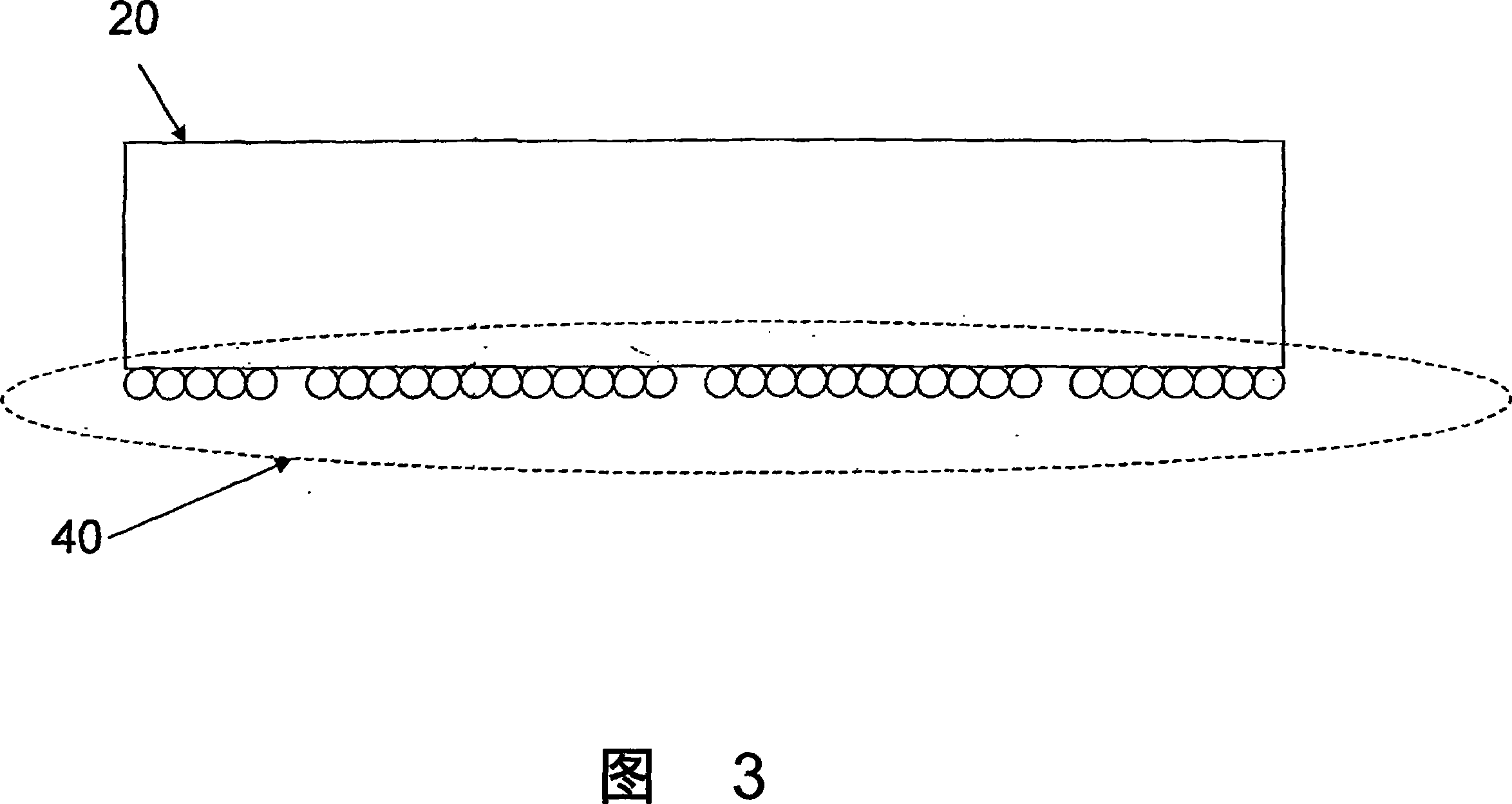
[0021] According to the present invention, a top-emitting OLED device is provided with a scattering layer to scatter the light generated by the light-emitting element, thereby weakening or eliminating Newton's rings. The scattering layer can be disposed within the cover surface of the OLED, outside the cover surface of the OLED, or on both the inner and outer surfaces. According to the invention, the scattering layer is provided such that the light transmitted through the cover glass is not weakened by the scattering layer. In one embodiment, the surface topography and scattering ability of the scattering layer are characterized such that the scattering layer has a rough surface. Additionally, various methods of providing a roughened surface are disclosed herein. The OLED device completed according to the present invention can be used in various applications, such as mobile phones, televisions, and the like.

[0022] According to the invention, a scattering layer is achieved...


PUM


Abstract

A technique for reducing the appearance of Newton' s rings for a light emitting device is disclosed. The light emitting device (10) comprises a scattering layer (50) positioned contiguous with the inner surface (40) of a cover substrate (20). Scattering the light reduces or eliminates the opportunity for constructive interference and as a result reduces or eliminates Newton' s ring formation.

Description

technical field [0001] The present invention relates to organic light emitting diodes (OLEDs). In particular, the present invention relates to methods and apparatus for eliminating Newton's rings in OLEDs. Background technique [0002] The combination of light reflected between two glass surfaces with different curvatures separated by an air gap of variable thickness creates visible interference patterns known as Newton's rings. Similarly, in a glass substrate with two approximately parallel faces, light may enter the glass substrate through the first face and generate a first reflection by reflecting at the first face of the glass substrate. The same light also reflects off the second side of the glass substrate, creating a second reflection. When the first reflected light and the second reflected light are combined in a constructive manner (that is, mutually consistent and superimposed, or constructively interfered), it can be seen from the first side of the glass substr...

Claims


Application Information

Patent Timeline
Patent Type & Authority Applications(China)
IPC IPC(8): H01L51/52
CPCG02B5/0226H01L51/5268H01L2251/5315H01L51/5237H01L51/5281G02B5/0284G02B5/0278H10K2102/3026H10K59/871H10K59/877Y10S428/917H10K50/854H10K50/86H10K50/841
Inventor H·D·博克R·A·朗根斯芬
Owner CORNING INC
Learn More