Low-leakage current thin film transistor circuit

A thin-film transistor and circuit technology, applied in the field of low-leakage current thin-film transistors, can solve problems such as lower aperture ratio and lower display brightness

Inactive Publication Date: 2005-01-19
TPO DISPLAY
View PDF0 Cites 8 Cited by
  • Summary
  • Abstract
  • Description
  • Claims
  • Application Information

AI Technical Summary

Problems solved by technology

Then the aperture ratio (aperture ratio) is reduced, so that the brightness of the display is greatly reduced, and it is easy to produce Newton ring effect (Newton ring effect) due to component reflection

Method used


Image

  • Low-leakage current thin film transistor circuit
  • Low-leakage current thin film transistor circuit
  • Low-leakage current thin film transistor circuit

Examples


Embodiment Construction

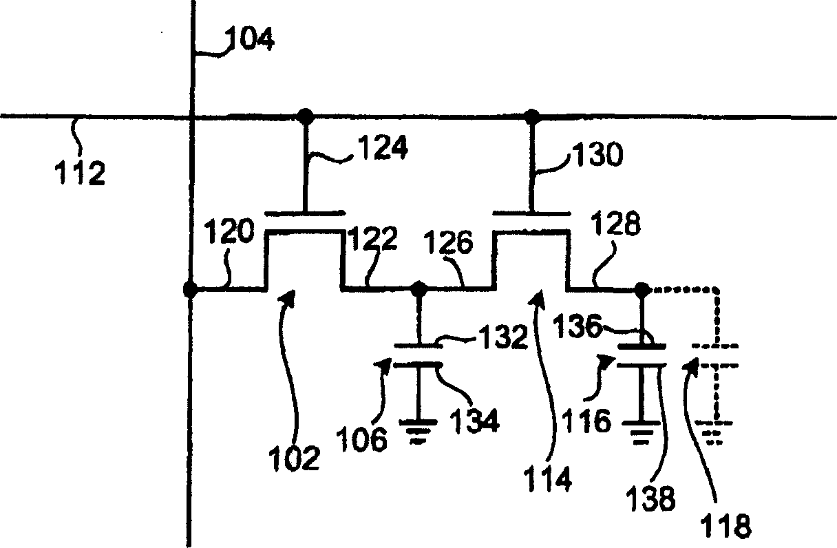
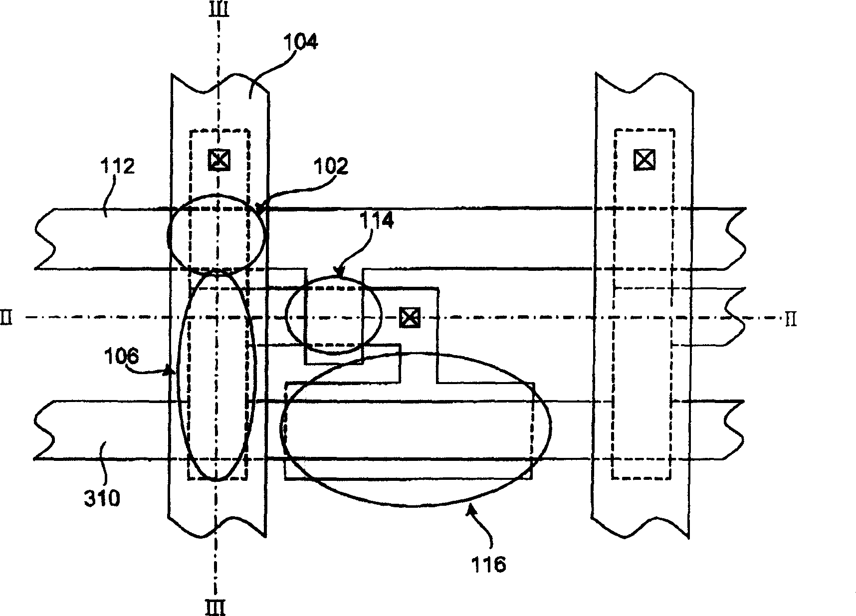
[0029] refer to figure 1 , image 3 , Figure 4 and Figure 5 . The invention provides a thin film transistor circuit, the schematic diagram of which is as follows figure 1 . The circuit includes a first thin film transistor 102 , a data line 104 and an adjustment capacitor 106 . Wherein the first thin film transistor 102 comprises a semiconductor layer 408 (such as Figure 4 shown) and a gate 124. The semiconductor layer 408 includes the drain region 120 and the source region 122 of the first thin film transistor 102 . The data line 104 is connected to the drain region 120 of the first TFT 102 . The first electrode 132 of the adjustment capacitor 106 is connected to the source region 122 of the first TFT 102 . The adjusting capacitor 106 is provided to reduce the leakage current.

[0030] The TFT circuit also includes a common line 310 (such as image 3 shown). The second electrode 134 of the adjustment capacitor 106 is connected to the common line 310 . The TFT ...


PUM


Abstract

This invention provides a kind of Low-Leakage-Current thin film transistor circuit. It can reduce the leakage current and not take up many pixel areas. It increases the open rate, reduces the Newton's ring effect. This circuit consists of a first film transistor, a datawire and a regulating capacitor. The first film transistor consists of a grid and a semi-conductor layer, which consists of a drain region and a source region. The datawire connects to the drain region of the first film transistor. The regulating capacitor includes a first electrode, which connects to the source region of the first film transistor. The part of the regulating capacitor is covered by datawire.

Description

technical field [0001] The invention relates to a thin film transistor (thin film transistor; TFT) circuit with low leakage current. Background technique [0002] Nowadays thin film transistors are widely used in displays. However, as the number of gray scales of the display increases, the requirement for low leakage current becomes more and more stringent. A schematic diagram of a circuit that can achieve low leakage current is shown in figure 1 . It can be seen that in addition to the common storage capacitor 116 (storage capacitor), there is an additional adjusting capacitor (adjusting capacitor) 106 . The adjustment capacitor 106 is located at the source 122 of the first TFT 102 . [0003] The top view of the configuration of the circuit in the prior art is as follows: figure 2 . It can be seen that the adjustment capacitor 206 and the storage capacitor 216 are located in the pixel. In this way, the adjustment capacitor 206 will occupy a part of the area of ​​the...

Claims


Application Information

Patent Timeline
Patent Type & Authority Applications(China)
IPC IPC(8): G09G5/00H01L29/786
Inventor 孟昭宇石安
Owner TPO DISPLAY
Why Eureka
Try Eureka