Method and device for processing bound link

A technology for bundling links and processing methods, applied in the direction of error prevention/detection using return channels, digital transmission systems, electrical components, etc., can solve problems such as service interruption, failure to automatically recover, and failure of BundleLink status to negotiate successfully. Quality requirements, fast recovery effect

Inactive Publication Date: 2007-12-26
HUAWEI TECH CO LTD
View PDF0 Cites 16 Cited by
  • Summary
  • Abstract
  • Description
  • Claims
  • Application Information

AI Technical Summary

Problems solved by technology

Repeatedly, the status of the Bundle Link between the A side and the B side can never be successfully negotiated
Therefore, when one end is in the ack rx state and the other end recovers from the initial state, the states of the A end and th

Method used


Image

  • Method and device for processing bound link
  • Method and device for processing bound link
  • Method and device for processing bound link

Examples


Embodiment Construction

[0039] The implementation of the present invention will be further described below in conjunction with the drawings and examples.

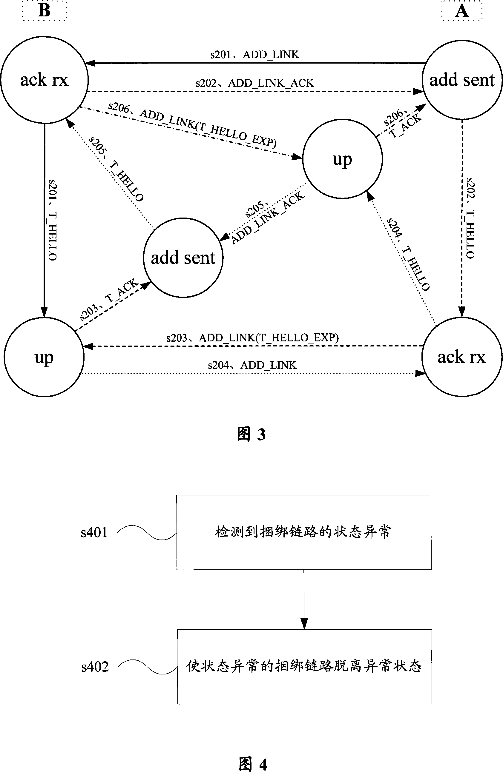
[0040] In Embodiment 1 of the present invention, a processing method for bundling links is shown in FIG. 4, including the following steps:

[0041] In step s401, it is detected that the state of the bundled link is abnormal.

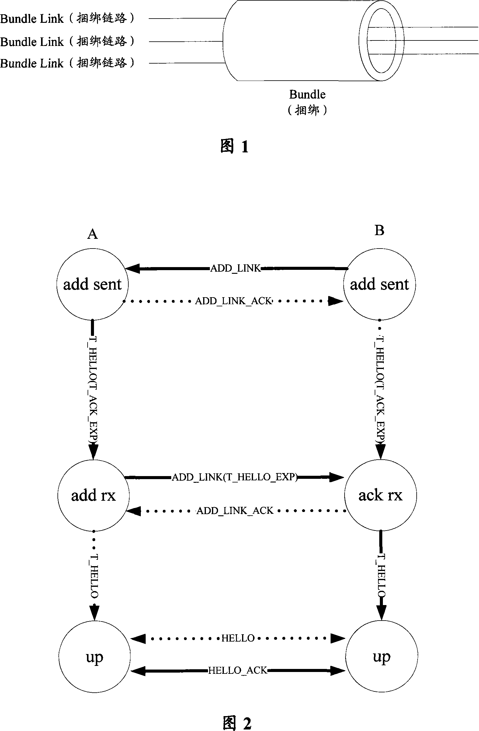
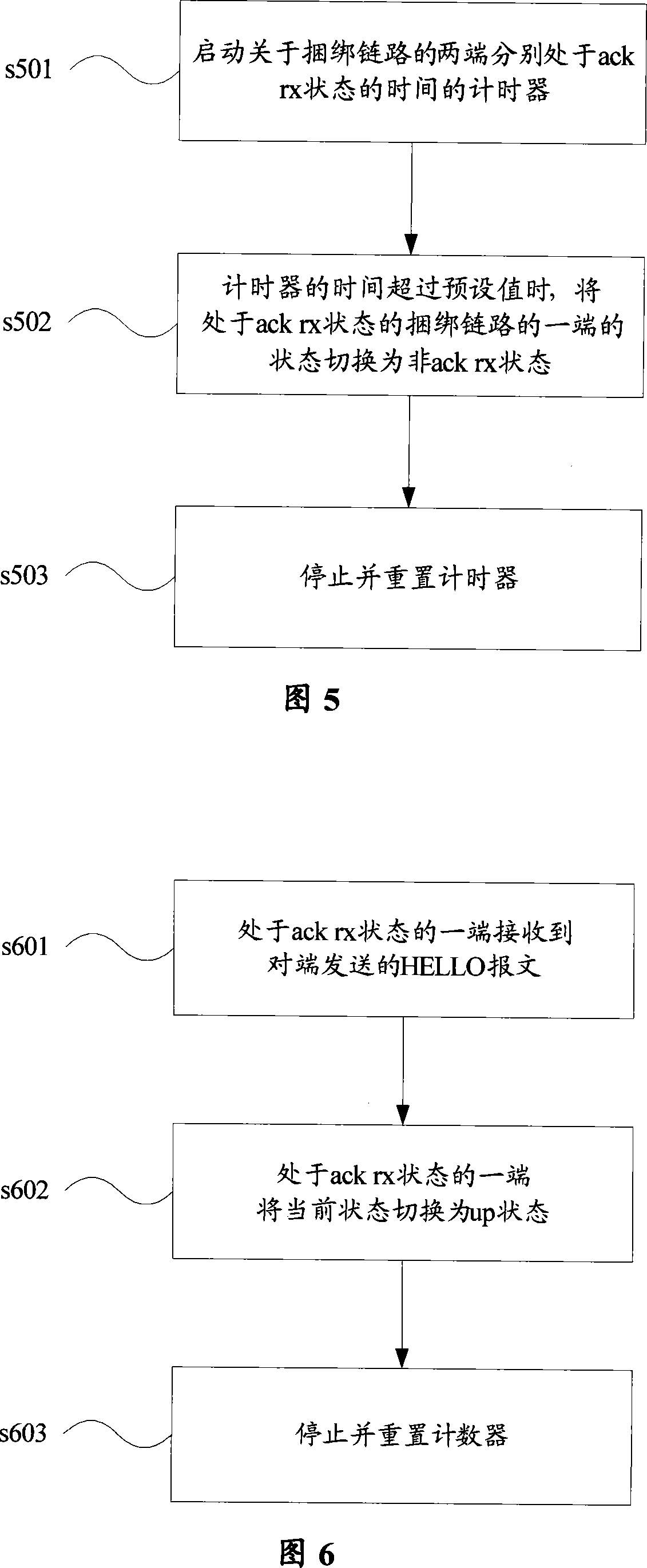
[0042] The abnormal status of both ends of the bundled link may be as described above: the time for either end of the bundled link to be in the ack rx state times out; or within a predetermined time, either end of the bundled link is in the state defined by the state machine The number of cyclic switching exceeds a preset value, and the cyclic state includes an ack rx state, an up state, and an add sent state.

[0043] Step s402, making the bundled link in abnormal state out of abnormal state.

[0044] The following describes a specific method for restoring the bundled link with an abnormal state in step s402 of the presen...


PUM


Abstract

The method comprises: after detecting the abnormal state of the binding link, letting the binding link in abnormal state to leave the abnormal state. The invention also provides an apparatus thereof.

Description

technical field [0001] The present invention relates to the technical field of communications, and in particular to a processing method and equipment for bundling links. Background technique [0002] Multilink Frame Relay MFR (Multilink Frame Relay) is a cost-effective bandwidth solution for Frame Relay users. It is implemented in UNI (User Network Interface, User Network Interface) / NNI (Network Node Interface, The multi-link frame relay function under the network node interface) interface. MFR provides a virtual physical interface for frame relay services: MFR interface, which is actually an interface composed of multiple real physical interfaces, which is called Bundle (bundle) in the protocol, and the components that make up the MFR interface Multiple physical interfaces are called Bundle Link, and the transmission bandwidth provided by the MFR interface for the upper-layer frame relay is almost the sum of the bandwidth of multiple physical interfaces it bundles. A sche...

Claims


Application Information

Patent Timeline
IPC IPC(8): H04L12/26H04L12/56H04L1/16
CPCH04L41/0677
Inventor 钱骁张炜李小军
Owner HUAWEI TECH CO LTD
Why Eureka
Try Eureka