
Stretching control method of the stretching unit of a spinning machine and a spinning machine

A technology of textile machinery and control methods, used in spinning machines, drafting equipment, textiles and papermaking, etc., can solve problems such as low optimal value of fiber sliver quality

Active Publication Date: 2010-12-08
RIETER INGOLSTADT SPINNEREI
View PDF9 Cites 0 Cited by
  • Summary
  • Abstract
  • Description
  • Claims
  • Application Information

AI Technical Summary

Problems solved by technology

This then often results in a suboptimal quality of the sliver exiting the drafting zone

Method used

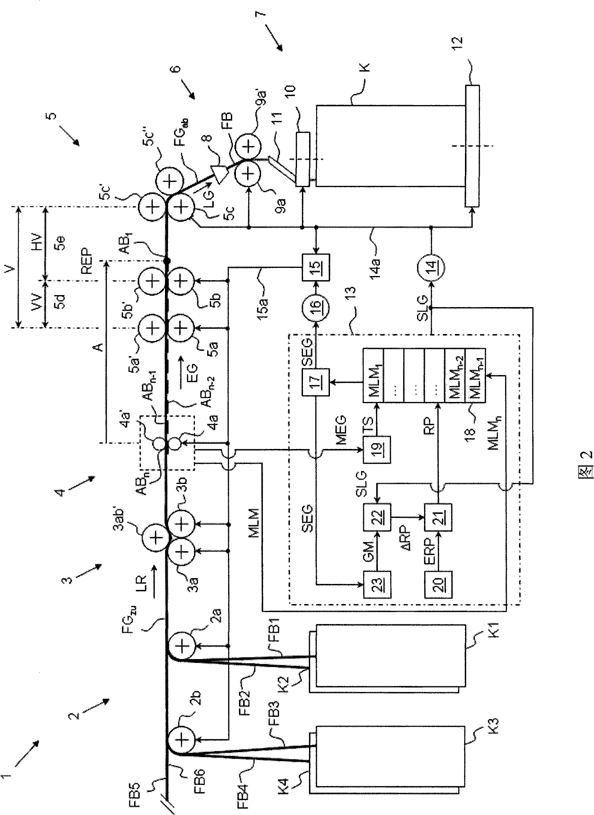
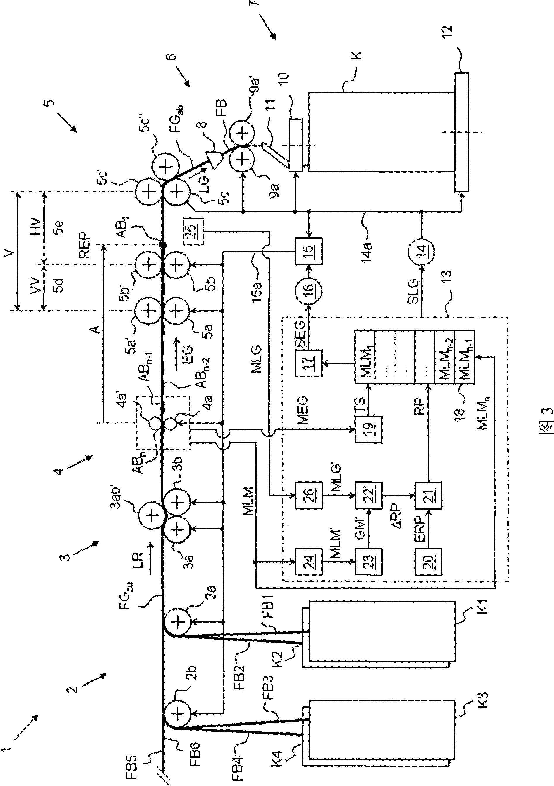

Image

  • Stretching control method of the stretching unit of a spinning machine and a spinning machine
  • Stretching control method of the stretching unit of a spinning machine and a spinning machine
  • Stretching control method of the stretching unit of a spinning machine and a spinning machine

Examples


Embodiment Construction

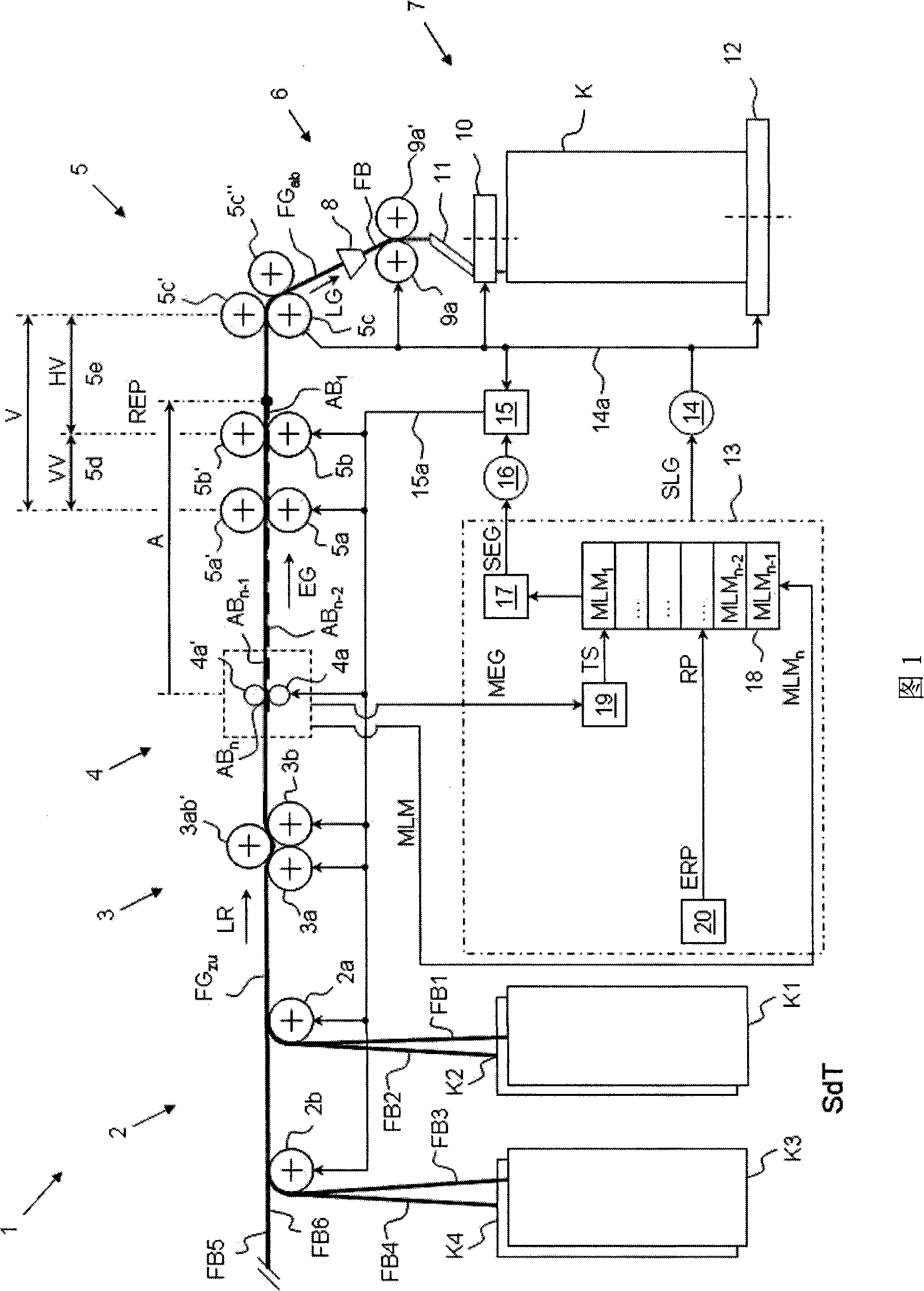
[0032] figure 1 is a schematic side view of a textile preparation machine 1 such as a draw frame 1 . The fiber strips FB1, FB2, FB3, FB4, FB5, FB6 located at the front of the draw frame 1 move along the direction of movement LR, on the feed stand 2 (feed stand), feed roller unit 3, feed sensor unit 4, draft System 5, exit guide 6 and sliver storage 7.

[0033] The only schematically shown guide table 2 comprises a first guide table roller 2a arranged in such a way that the first fiber strip FB1 located at the front of the machine can be drawn starting from the can K1 provided on the draw frame 1, At the same time the second fiber strand FB2 can be drawn starting from the can K2 in the offset position. Also included is a second guide table roller 2b for drafting a third fiber strand FB3 from a third drum K3 and a fourth fiber strand FB4 from a fourth drum K4. The fifth fiber strip FB5 and the sixth fiber strip FB6 are also drafted from other cans (not shown) by other guide t...


PUM


Abstract

The present invention provides a drafting controlling method for the drafting system (5) of the textile machinery (1), wherein, for the continuous fragments (AB1, ellipsis, ABn-2, ABn-1, ABn) of the fiber strip (FGzu) of the inputting drafting system (5), the feeding sensor unit (4) at the upriver of the drafting system (5) gets the measured value (MLM1, ellipsis, MLMn-2, MLMn-1, MLMn) of weight at unit length of each fragment; to regulate the weight at unit length of the inputting fiber strip (FGzu) when the fragment (AB1) which is relative to a certain measured value (MLM1) reaches a control action point (REP) assigned by the appointed control value (MLM1), it will do controlling and regulation to the drafting (V) of the drafting system (5) on the basis of the measured value (MLM1); it modifies the appointed value (RP) used to control the action point (REP) in the making process of the textile machinery (1), wherein, the appointed value (RP) is from the predefined setting value (ERP) and corrected value (delta RP), at the same time the corrected value (delta RP) is confirmed by the values (MEG, GM, GM', SEG) relative to the feeding velocity (EG) of the fiber strip (FGzu) of the inputting drafting system (5) and the values (MLG, SLG) relative to the outputting velocity (LG) of the fiber strip (FGab) of the outputting drafting system (5). The invention also provides a textile machinery.

Description

technical field [0001] The invention relates to a drafting control method for a drafting system of a textile machine, and a textile machine according to the independent claims. Background technique [0002] Textile machines comprising a drafting system with a draft whose working process is constant when adjustable, other than textile machines having a drafting system with a controlled draft, in other words drafting It is known in the prior art that the extension can change during operation. An important aspect of controlling drafting in a drafting system of a textile machine is the position of what is known as the control action point. The control action point is the designated position upstream of the drafting system, where a portion of the sliver (whose weight per unit length has been measured) is positioned when adjusting the drafting of the draw frame. The purpose of controlling and adjusting is to even out the weight per unit length of the fiber strip. [0003] The p...

Claims


Application Information

Patent Timeline
Patent Type & Authority Patents(China)
IPC IPC(8): D01H5/38D01G15/12
CPCD01H5/32D01H5/42D01H5/38
Inventor 不公告发明人
Owner RIETER INGOLSTADT SPINNEREI
Learn More