Pipe tail low heat loss medium transfer sun vacuum energy changing hot pipe
A heat pipe and sun technology, applied in the field of solar energy applications, can solve the problems of tail end heat loss, system paralysis, low glass pressure bearing capacity, etc., and achieve the effects of high safety, low tail consumption and easy processing.
- Summary
- Abstract
- Description
- Claims
- Application Information
AI Technical Summary
Problems solved by technology
Method used
Image
Examples
no. 1 example
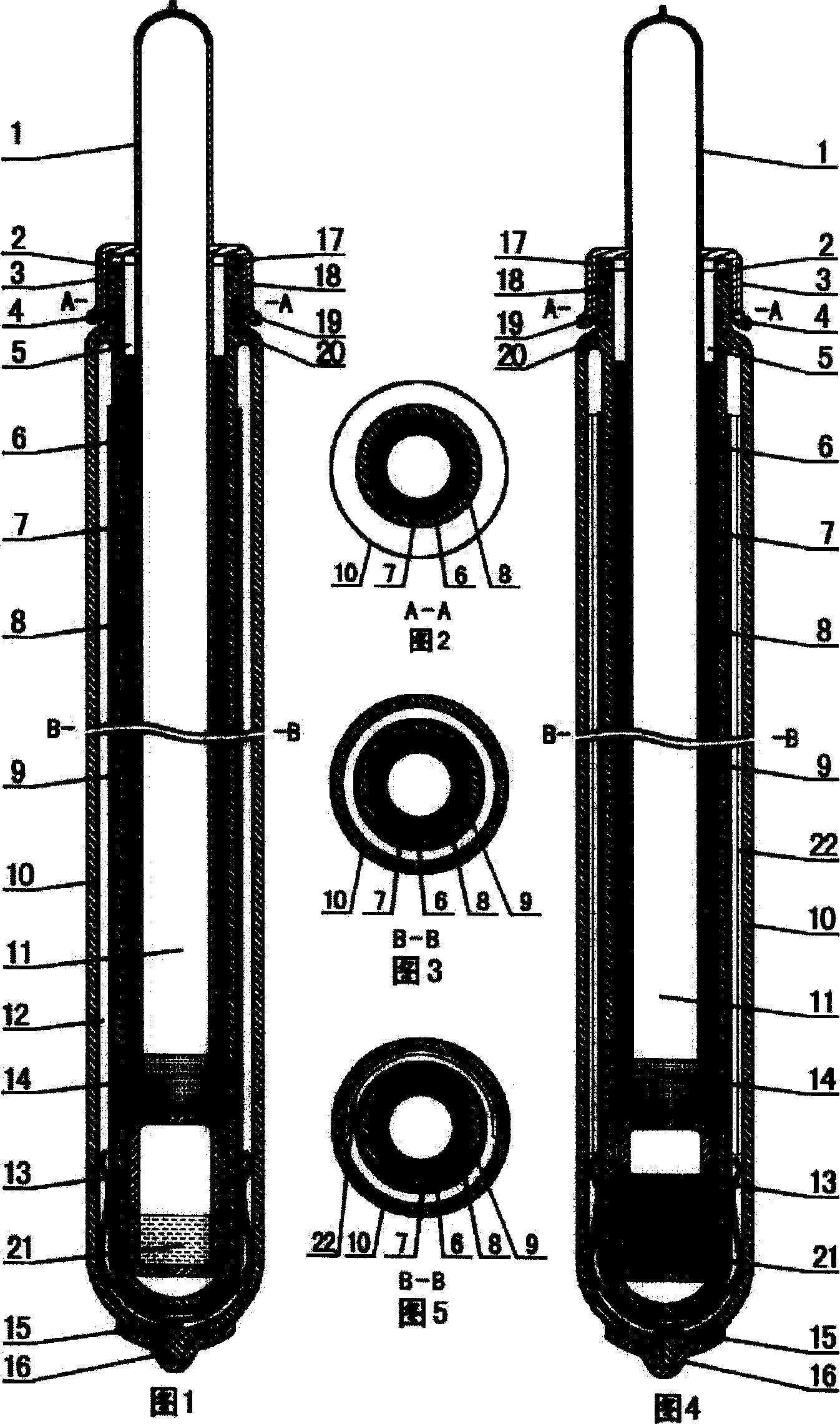
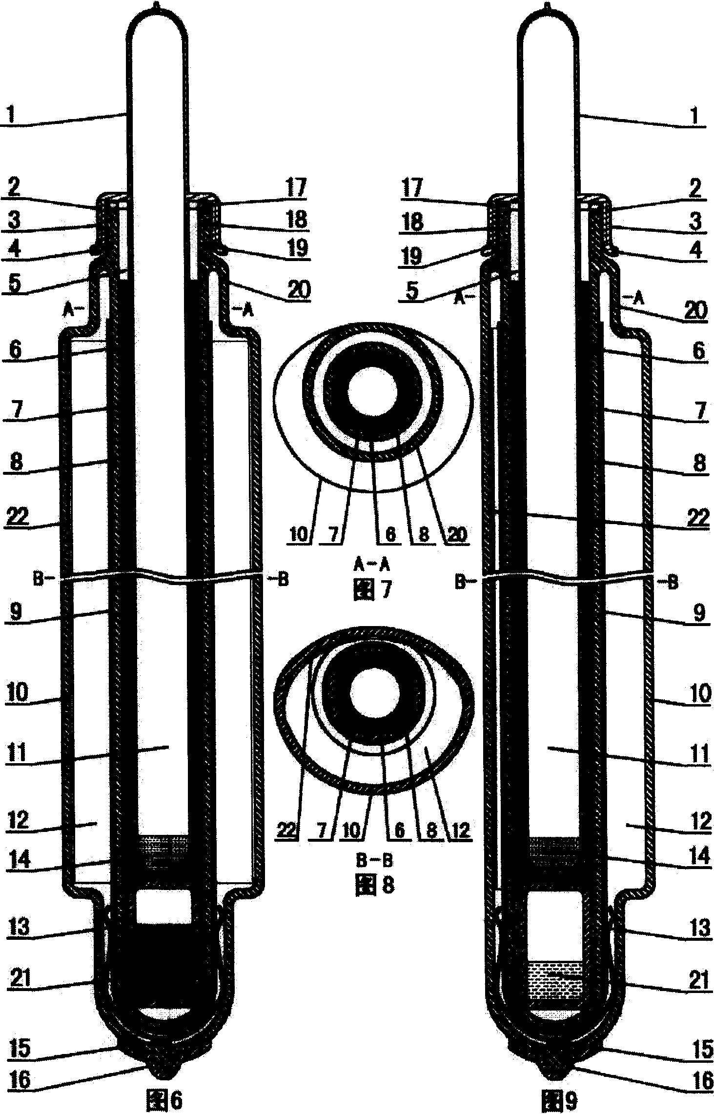
[0063] In the first embodiment: a low-heat-loss medium conduction solar vacuum energy conversion heat pipe at the end of the tube includes a reduced-diameter nozzle 18, a variable-diameter curved surface transition tube 20, a small diameter inner glass tube 8, an outer glass tube 10, and a solar vacuum energy conversion tube. Heat pipe heat-absorbing film 9, elastic metal support card 13, getter 15, exhaust nozzle 16, heat pipe 6, heat-conducting material 7, one end of the small-diameter inner glass tube 8 coated with solar vacuum heat pipe heat-absorbing film 9 The tube head is sealed by glass welding, and the large diameter outer glass tube 10 with an exhaust nozzle 16 on one end of the tube head is welded with glass. , the other end is annularly welded with the outer glass tube 10 and the transition tube 20 with a reduced diameter curved surface, and the reduced diameter nozzle 18, and the reduced diameter nozzle 18 is provided with an external thread 19. Vacuum the solar v...
no. 3 example
[0065] In the third embodiment: the cross-section of the outer glass tube 10 of the solar vacuum heat exchange heat pipe is an elliptical special-shaped tube. Others are equal to the second embodiment.
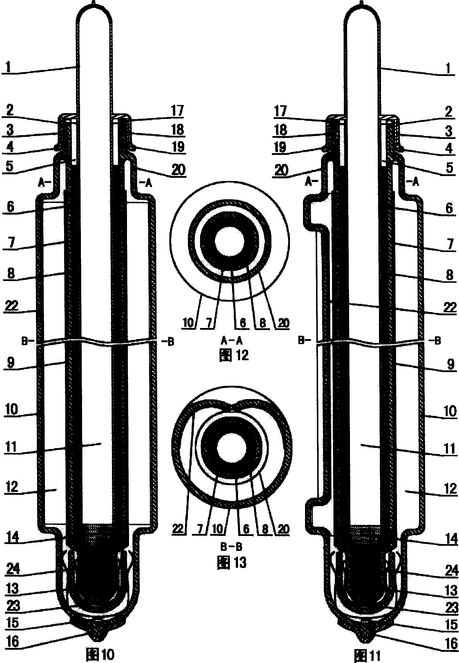
[0066] In the fourth embodiment: the cross-section of the outer glass tube 9 of the solar vacuum heat transfer heat pipe is an ω-shaped special-shaped pipe, and a heat preservation spacer 23 is installed in the bottom vacuum chamber of the solar vacuum heat transfer heat pipe, and the inner wall of the heat preservation spacer 23 passes through the inner wall The metal support elastic clip 24 is in contact with the closed end of the tail of the inner glass tube 8, and the inner wall of the closed end of the outer glass tube 10 at the tail of the solar vacuum heat pipe is supported and fixed by the elastic metal support clip 13 and the outer wall of the insulation spacer 23. Others are equal to the second embodiment.
no. 5 example
[0067] In the fifth embodiment: the solar vacuum heat transfer heat pipe is equipped with a concentrating device 21, and the bottom of the small-diameter inner glass tube 8 of the solar vacuum heat transfer heat pipe is sealed with a thermal insulation compartment 25, and the others are the same as the second embodiment.
[0068] In the sixth embodiment: the bottom of the lumen of the solar vacuum energy exchange heat pipe is equipped with a solar vacuum energy exchange heat pipe heat conduction incubator 21, an insulation spacer 23 is installed in the bottom adiabatic vacuum chamber 12, and a polycarbonate is inserted in the solar vacuum energy exchange heat pipe. light device 21 . Others are equivalent to the fourth embodiment.
[0069] In the seventh embodiment: the cross-section of the outer glass tube 10 of the solar vacuum heat exchange heat pipe is The bottom of the small diameter inner glass tube 8 of the positive vacuum energy-transforming heat pipe is packaged with...
PUM
 Abstract
Description
Claims
Application Information
 - R&D
- Intellectual Property
- Life Sciences
- Materials
- Tech Scout
- Unparalleled Data Quality
- Higher Quality Content
- 60% Fewer Hallucinations
Browse by: Latest US Patents, China's latest patents, Technical Efficacy Thesaurus, Application Domain, Technology Topic, Popular Technical Reports.
© 2025 PatSnap. All rights reserved.Legal|Privacy policy|Modern Slavery Act Transparency Statement|Sitemap|About US| Contact US: help@patsnap.com


