Telescopic brake bar

A telescopic and brake rod technology, which is applied to the connection of rods, connecting components, road railings, etc., can solve the problems of time-consuming and laborious, elongated or shortened brake rods, and poor structural flexibility, so as to enhance practicability and reduce packaging , the effect of a reasonable structure

Inactive Publication Date: 2008-01-09
深圳市威捷机电技术有限公司
View PDF0 Cites 7 Cited by
  • Summary
  • Abstract
  • Description
  • Claims
  • Application Information

AI Technical Summary

Problems solved by technology

[0002] The gate bar of existing barrier gates is generally a fixed length through bar, which causes many inconveniences such as packaging, transportation and installation. When using narrow streets or alleys, it will not only take time and effort, but also affect the normal traffic order, and also increase the packaging costs and costs of the barriers; more importantly, due to the fixed length of the barrier, the width of different sites , area size and other factors are uncertain. Moreover, there is inevitably a certain error between actual measurement, theoretical calculation and actual i

Method used


Image

  • Telescopic brake bar

Examples


Embodiment Construction

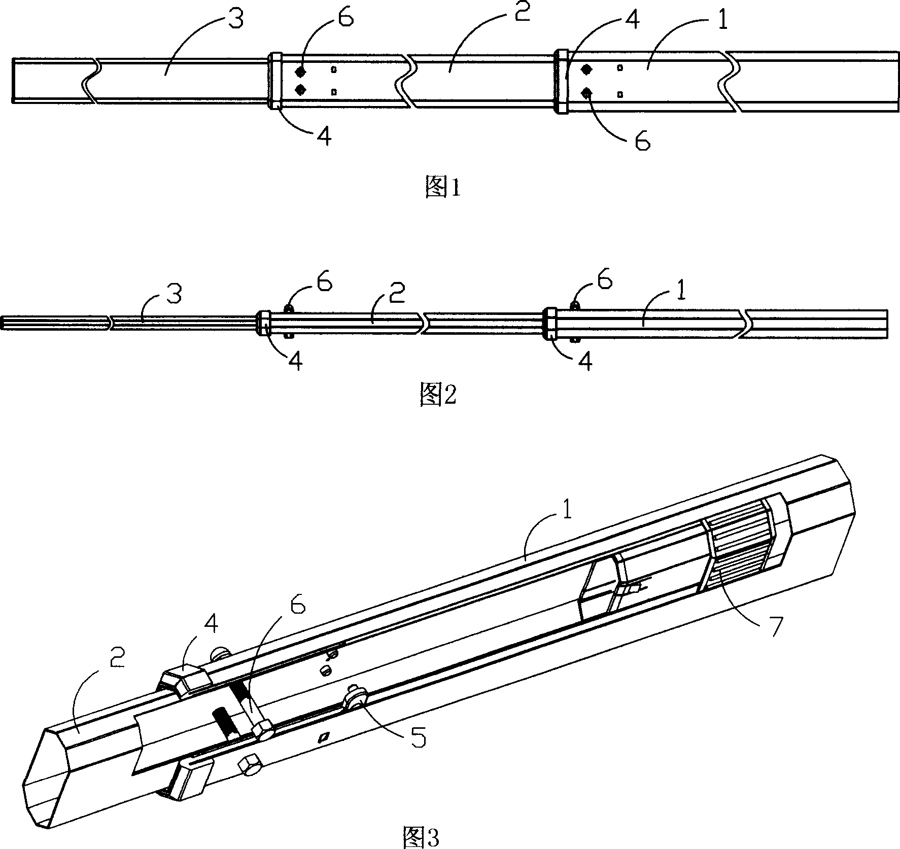
[0011] A telescopic brake rod as shown in Fig. 1 and Fig. 2 includes a main rod 1, a plurality of sleeve rods 2 and a front rod 3 that are telescopically limited and socketed in sequence, and, between the adjacent main rod 1 and the sleeve A positioning device is provided at any overlap between the rod 2 and the sleeve rod 2 and the front rod 3 .

[0012] The present invention will be described in detail below by taking a section of the sleeve rod as an example: as shown in Figure 3, a limit plastic sleeve 4 is respectively provided on both sides of the front end of the main rod 1 and the sleeve rod 2, and the sleeve rod 2 and the front rod 3 The side wall is symmetrically provided with a limit plastic block 5 corresponding to the limit plastic sleeve 4. When in use, when the front rod 1 or the sleeve rod 2 is stretched to a certain length, the limit plastic sleeve 4 will block the limit plastic block 5 Continue to slide forward to effectively hinder the stretching of the brak...


PUM


Abstract

The telescopic gate rod capable of being regulated to and located in different required length flexibly includes one main rod, several sleeves and one front rod socketed successively, as well as locating units set between two adjacent said parts. It may be used in different fields of different sizes, and is practical.

Description

technical field [0001] The present invention relates to a gate bar of a barrier gate, specifically, it relates to a pole that can be positioned according to the actual needs of users, and can be installed and used in various places through specific adjustments, and is convenient and flexible to install and use. A telescopic brake lever. Background technique [0002] The gate bar of existing barrier gates is generally a fixed length through bar, which causes many inconveniences such as packaging, transportation and installation. When using narrow streets or alleys, it will not only take time and effort, but also affect the normal traffic order, and also increase the packaging costs and costs of the barriers; more importantly, due to the fixed length of the barrier, the width of different sites , area size and other factors are uncertain. Moreover, there is inevitably a certain error between actual measurement, theoretical calculation and actual installation. Therefore, when ...

Claims


Application Information

Patent Timeline
IPC IPC(8): B61L29/04F16B7/10
Inventor 涂启纯饶金平
Owner 深圳市威捷机电技术有限公司
Why Eureka
Try Eureka