Waterpower pulse cavitation jet well drilling device and drill bit
A hydraulic pulse and cavitation technology, which is applied in the direction of liquid/gas jet drilling, drill bits, drilling equipment, etc., can solve the problems of poor hydraulic pulse effect, reduced hydraulic energy of the drill bit, and reduced jet impact effect, etc., achieving broad application prospects and development potential, good economic and social benefits, and the effect of increasing the ROP
- Summary
- Abstract
- Description
- Claims
- Application Information
AI Technical Summary
Problems solved by technology
Method used
Image
Examples
Embodiment 1
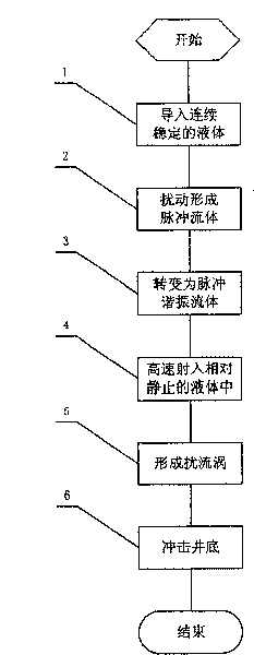
[0035] figure 1 It is a flow chart of Embodiment 1 of the method of the present invention. The specific steps of the method for hydraulic pulse cavitation jet drilling are as follows:
[0036] Step 101: During the drilling operation, converting the continuous and steady liquid flow used for impacting the bottom of the well into a pulsed resonance flow liquid;
[0037] Step 102: Injecting the pulse resonance flowing liquid into a relatively static liquid at high speed to generate cavitation;
[0038] Step 103: Impacting the pulsed resonance flow liquid that generates cavitation to the bottom of the well in the form of fluctuating pressure.
[0039] In the above preferred embodiment, the pulsating liquid flow can be generated by periodically disturbing the continuous and stable liquid flow according to a preset frequency.
[0040] In the above embodiment, the continuous fluid passes through the resonant cavity to form acoustic resonance, so that the jet flow at the outlet of ...
Embodiment 2
[0043] This embodiment is a process flow of a more detailed solution than that of Embodiment 1. details as follows:
[0044] Step 1010: During the drilling operation, converting the continuous and stable liquid flow used for impacting the bottom of the well into a pulse resonance flowing liquid; periodically disturbing the continuous and stable liquid flow according to a preset frequency;
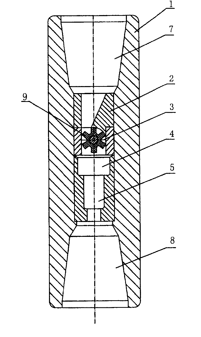
[0045] Step 1021: the organ pipe resonant cavity can form acoustic resonance, so that the jet flow at the outlet of the nozzle becomes intermittent vortex circulation, and cavitation is induced;
[0046] Step 1022, the rotating impeller can generate disturbance to the continuous fluid, enhance the discontinuity of the fluid, thereby enhancing the cavitation;
[0047] Step 1031: fluctuate the pressure of the pulse resonance flowing liquid;
[0048] Step 1032: Make the pulsed resonant flow liquid with pressure fluctuations generate feedback pressure resonance;
[0049] Step 1033: Using the p...
Embodiment 3
[0054] This example is based on Figure 13 When assembling and using, the specific steps are as follows:
[0055] Step 201, during the drilling operation of the drilling tool, introducing a continuous and stable liquid flow for impacting the bottom of the well;
[0056] Step 202, periodically disturbing the continuous and stable liquid flow to form a pulsed flow liquid to increase the impact effect;
[0057] Step 203, amplifying the pulsating liquid and causing it to resonate, thus transforming it into a pulsating resonant flowing liquid;
[0058] Step 204, by reducing the cross-sectional area of the fluid and accelerating its flow velocity, injecting it into the relatively static ambient liquid at high speed;
[0059] Step 205, making the liquid form a turbulent vortex to generate cavitation;
[0060] Step 206, flowing the high-speed pulse resonant flow liquid that produces cavitation into the organ pipe nozzle on the drill bit in the form of fluctuating pressure;
[00...
PUM
 Abstract
Description
Claims
Application Information
 - R&D
- Intellectual Property
- Life Sciences
- Materials
- Tech Scout
- Unparalleled Data Quality
- Higher Quality Content
- 60% Fewer Hallucinations
Browse by: Latest US Patents, China's latest patents, Technical Efficacy Thesaurus, Application Domain, Technology Topic, Popular Technical Reports.
© 2025 PatSnap. All rights reserved.Legal|Privacy policy|Modern Slavery Act Transparency Statement|Sitemap|About US| Contact US: help@patsnap.com


