Air conditioner

An air conditioner, air technology, applied in the direction of air conditioning systems, space heating and ventilation, space heating and ventilation details, etc., can solve the problem of inability to improve cooling or heating efficiency, installation location restrictions, difficulty in improving internal appearance and effective use of indoor space Space and other issues

Inactive Publication Date: 2008-01-16
LG ELECTRONICS INC
View PDF0 Cites 53 Cited by
  • Summary
  • Abstract
  • Description
  • Claims
  • Application Information

AI Technical Summary

Problems solved by technology

As a result, the direction of the exhausted air flow is restricted and constant, and cooling or heating efficiency cannot be improved
[0009] In addition, due to the direction of the discharged air flow, the installation position of the indoor unit of the conventional air conditioner is limited
Therefore, it is difficult to improve the internal appearance and effectively utilize the interior space

Method used


Image

  • Air conditioner
  • Air conditioner
  • Air conditioner

Examples


Embodiment Construction

[0071] An air conditioner according to a preferred embodiment of the present invention will now be described in detail with reference to the accompanying drawings.

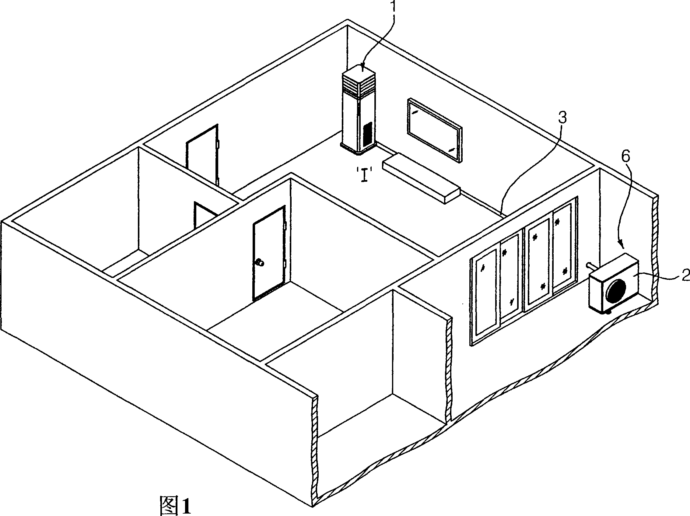
[0072] FIG. 1 is a view showing installation of an indoor unit of an air conditioner according to the present invention.

[0073] At least one indoor unit 1 of the air conditioner is installed in the indoor space I requiring air conditioning, and is connected to at least one outdoor unit 2 installed outside the indoor space I through a refrigerant pipe 3 for cooling, heating or purifying the indoor space I. For ease of illustration, it is conceivable that one indoor unit 1 and one outdoor unit 2 are installed.

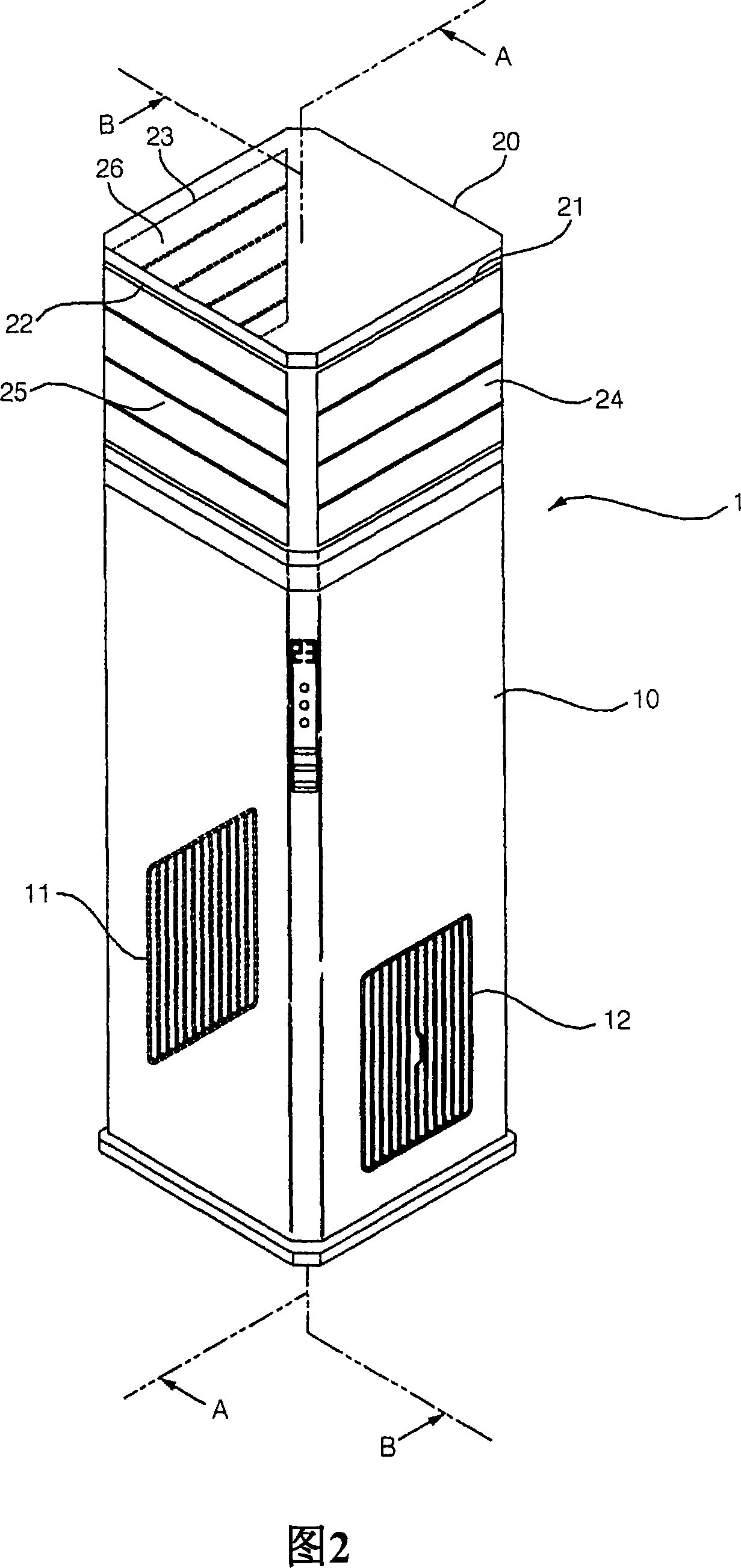
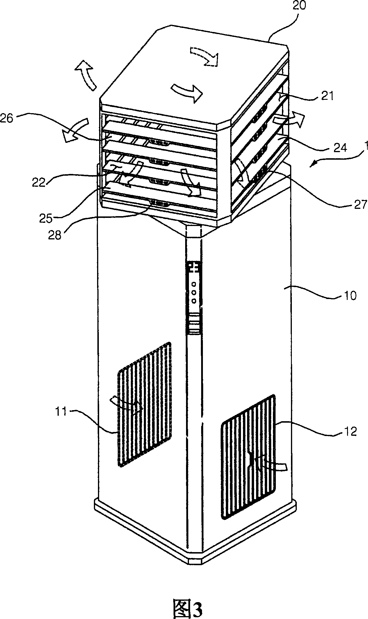
[0074] 2 shows a perspective view of the indoor unit of the air conditioner according to the first embodiment of the present invention when it is not in operation, and FIG. 3 shows a perspective view of the indoor unit of the air conditioner according to the first embodiment of the present invention when ...


PUM


Abstract

The present invention discloses an air conditioner, including: a suction hole; a blower positioned to suck the air through the suction hole; a heat exchanger positioned to exchange heat with the air sucked by the blower; a passage extended to transfer the air from the suction hole to the blower and the heat exchanger, one end of the passage being opened; and at least one discharge hole positioned with a gap from the opened end, for discharging the air heat-exchanged in the heat exchanger, the at least one discharge hole being rotatable relatively to the opened end.

Description

technical field [0001] The present invention relates to an air conditioner, and more particularly, to an indoor unit of the air conditioner capable of rotating a discharge hole for discharging heat-exchanged air relative to a main body of the air conditioner. Background technique [0002] Fig. 19 is a perspective view of a conventional air conditioner. [0003] Referring to FIG. 19, in the indoor unit of a conventional air conditioner, a front central discharge hole 702 is formed at the central portion of the front upper portion of a cabinet 700 constituting the appearance, and front right and front left discharge holes 704 are respectively formed at the top of the cabinet 700. On both sides of the front upper part, and left and right suction holes 706 are formed on both sides of the front lower part of the cabinet 700, respectively. [0004] A discharge grill 710 for dispersing air discharged through the front center discharge hole 702 is provided on the front center disch...

Claims


Application Information

Patent Timeline
Patent Type & Authority Applications(China)
IPC IPC(8): F24F1/00F24F13/00F24F13/08
CPCF24F1/0014F24F1/005F24F13/10F24F13/1413F24F2013/1446
Inventor 金正勋禹亨注金江永朴来贤宋惠映张圭燮金世显洪宁基
Owner LG ELECTRONICS INC
Why Eureka
Try Eureka