Turbine blade fatigue life evaluating method

A turbine blade, fatigue life technology, applied in the direction of engine life extension, blade support components, mechanical parts testing, etc., can solve the problems that have not been developed to quantitatively evaluate the fatigue life of turbine blade 1, gas turbine damage, etc.

Active Publication Date: 2008-01-16
MITSUBISHI HITACHIPOWER SYST LTD
View PDF0 Cites 13 Cited by
  • Summary
  • Abstract
  • Description
  • Claims
  • Application Information

AI Technical Summary

Problems solved by technology

[0006] However, in the above-mentioned gas turbine, a method for quantitatively evaluating and dealing with the fatigue life of the turbine blade 1 has not been developed; therefore, if a creep defect occurs suddenly, the entire gas turbine may be damaged

Method used


Image

  • Turbine blade fatigue life evaluating method
  • Turbine blade fatigue life evaluating method
  • Turbine blade fatigue life evaluating method

Examples


Embodiment Construction

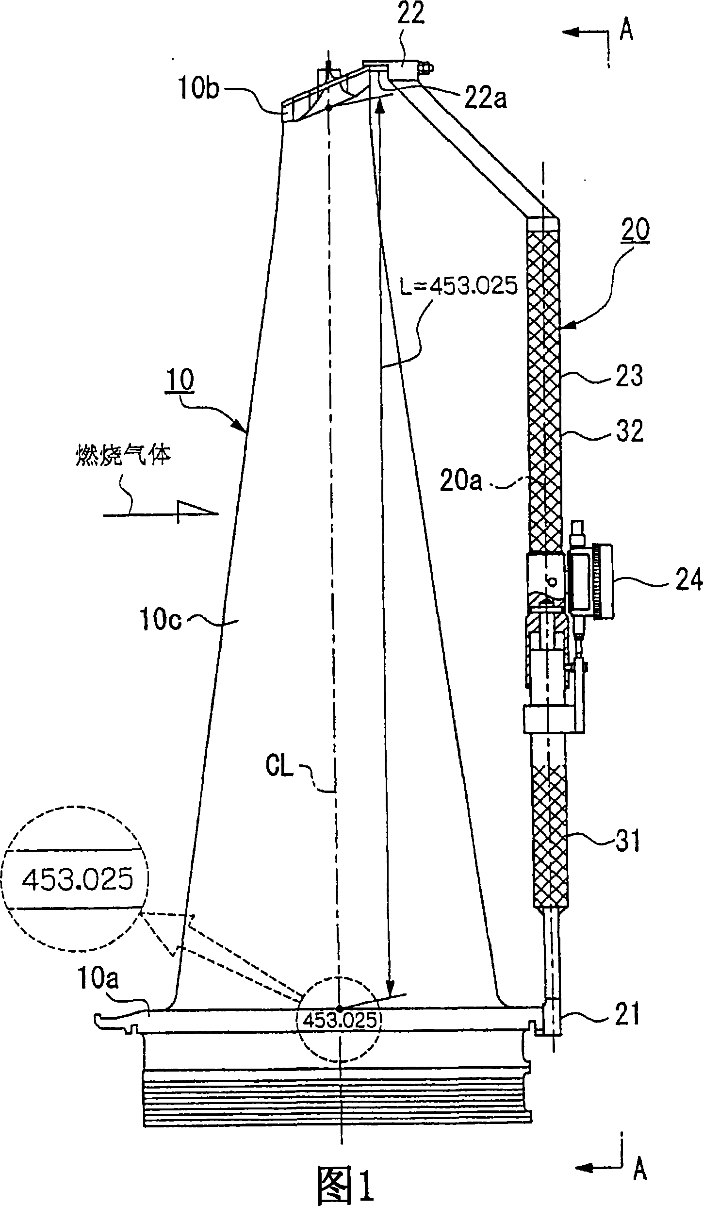
[0025] An embodiment of the turbine blade fatigue life evaluation method using the turbine blade creep elongation strain measuring device of the present invention and the turbine blade evaluated by the above method will be described with reference to the following drawings. In addition, the specific structural and functional descriptions set forth herein are representative only and do not limit the scope of the present invention.

[0026] The turbine blade of the present invention is not shown in the drawings, and is a member constituting a part of the turbine in a gas turbine including a compressor, a combustor, and a turbine. A rotor is axially supported for rotation within the turbine, and a plurality of turbine blades are secured around the rotor. In addition, the turbine causes the combustion gas generated in the combustion chamber to enter the combustion gas flow passage to expand. In addition, the rotor is rotated by blowing combustion gas against each turbine blade, a...


PUM


Abstract

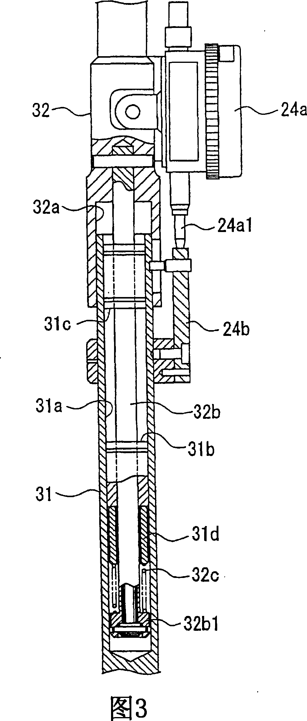
In order to provide a turbine blade fatigue life evaluating method for quantitively evaluating the fatigue life of a turbine blade, the turbine blade is determined to be within its fatigue life if the creep elongation strain in the longitudinal direction of the turbine blade is less than 0.5% of an initial length, and is determined to exceed its fatigue life if the creep elongation strain is 0.5% or more than the initial length. A turbine blade creep elongation strain measuring apparatus 20 comprises a first fixed end 21, a second fixed end 22, and a dial gauge 24. A dimension in the longitudinal direction is stamped on the surface of a turbine blade.

Description

[0001] Description of divisional application [0002] This application is a divisional case of a Chinese invention patent application with an application date of January 20, 2004, an application number of 200410002434.1, and an invention title of "Turbine Blade Fatigue Life Evaluation Method, Turbine Blade Creep Elongation Strain Measurement Device, and Turbine Blade" Apply. technical field [0003] The invention relates to a method for evaluating the fatigue life of a turbine blade. Background technique [0004] A gas turbine includes a compressor, a combustor, and a turbine (not shown). According to this gas turbine, the air compressed in the compressor is supplied to the combustor, and the compressed air is mixed with fuel supplied separately and combusted. Combustion gas generated in the combustion chamber is supplied to the turbine to generate rotational driving force in the turbine. [0005] FIG. 6 shows an example of the internal structure of the aforementioned tur...

Claims


Application Information

Patent Timeline
Patent Type & Authority Applications(China)
IPC IPC(8): G01M19/00G01B21/32F01D5/14G01M99/00F01D21/00G01B5/30G01M13/00
CPCF01D21/003F05B2260/80G01B5/205G01M13/00F05D2270/11F05B2270/109F05D2260/80G01B5/30
Inventor 弗里德里希·泽希廷查尔斯·埃利斯富田康意德永有吾
Owner MITSUBISHI HITACHIPOWER SYST LTD
Why Eureka
Try Eureka