
Packet transfer device and communication system

A communication system and packet transmission technology, applied in the field of packet transmission devices and communication systems, can solve problems such as large transmission delay and delay, and achieve the effects of reducing transmission delay, ensuring security, and preventing quality deterioration

Inactive Publication Date: 2008-01-16
HITACHI LTD
View PDF0 Cites 8 Cited by
  • Summary
  • Abstract
  • Description
  • Claims
  • Application Information

AI Technical Summary

Problems solved by technology

There is no problem when the network is idle, but sometimes there is a delay due to the insertion of other packets when the network is mixed
In addition, in a multi-stage L2SW network configured with uplink VLAN settings, the more devices used to relay IP packets, the greater the transmission delay, and audio delay becomes a problem

Method used


Image

  • Packet transfer device and communication system
  • Packet transfer device and communication system
  • Packet transfer device and communication system

Examples


Embodiment Construction

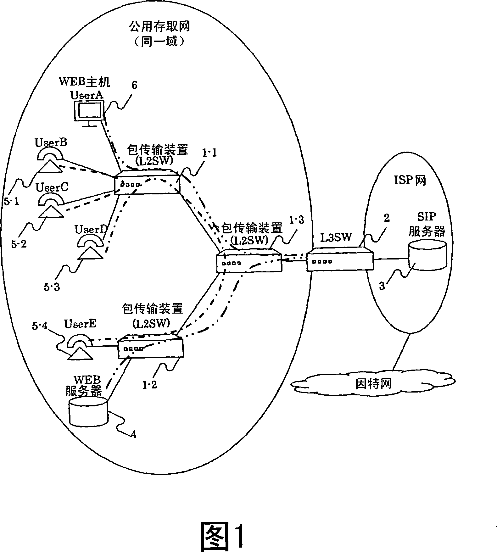
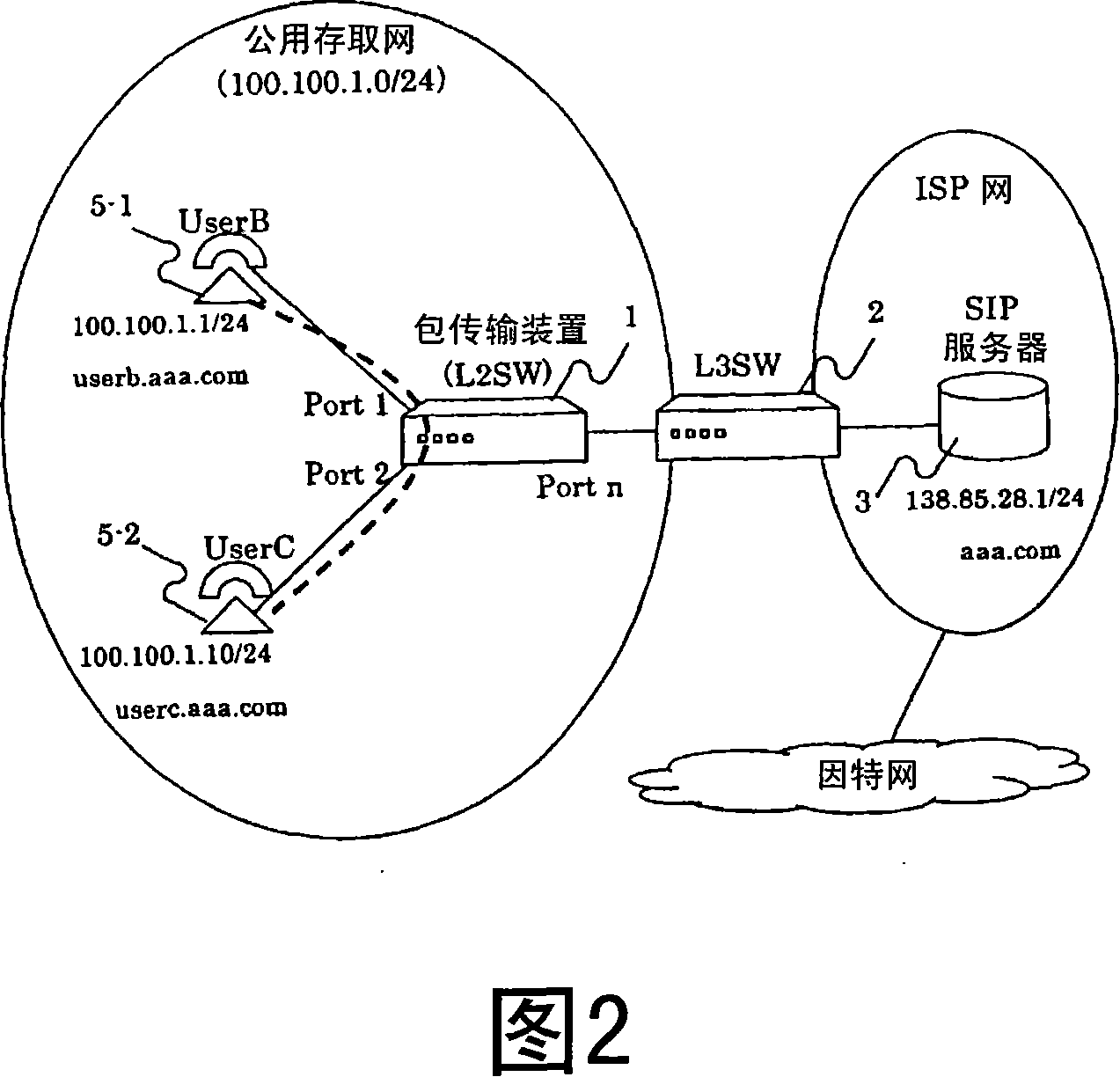
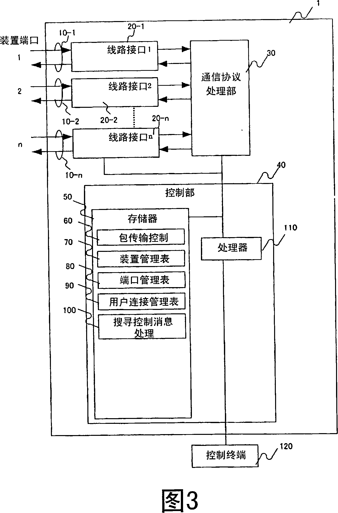
[0053] FIG. 1 is a configuration diagram of a communication system according to this embodiment. This communication system has a packet transmission device (first packet transmission device) (1), L3SW (Layer 3 switch: layer 3 switch, second packet transmission device) (2), SIP server (3) and SIP device terminal (5) . In addition, the communication system may further include a WEB server (4) and a WEB host (6).

[0054] In FIG. 1, the packet transmission device (1) has a SIP snooping function described later, and constitutes a wide-area L2 switching network (public access network). A WEB host (6), SIP device terminals (5-1, 5-2, 5-3, 5-4) and a WEB server (4) are accommodated in the public access network. In order for the SIP device terminal (5) connected to the public access network to access the SIP server (3) accommodated in the ISP network, an L3SW (2) is connected between the public access network and the ISP network. An example of communication between each terminal de...


PUM


Abstract

In a network having an L2SW in which uplink VLAN is set, a transfer delay of a voice call packet is prevented. In a process of establishing a session between terminals ( 5 ), a packet transfer device ( 1 ) stores information capable of specifying a sending terminal ( 5 - 1 ) and a receiving terminal ( 5 - 2 ) and a correspondence relation (user connection information) to a connection port into a table. A SIP message of a session control packet communicated between the terminals ( 5 ) is snooped, and a destination IP address, a transmission source IP address, a destination port number, a transmission source port number, a connection port etc. are stored into the table. In a case where an RTP packet as voice data is received after the session is established, the packet transfer device ( 1 ) performs a loopback transfer or transfers it to an uplink port in accordance with the table.

Description

technical field [0001] The present invention relates to a packet transmission device and a communication system, in particular to a packet that can effectively reduce transmission delay time when VoIP communication is performed between SIP device terminals connected to the same packet transmission device of Ethernet (registered trademark) through a virtual communication path. Transmission device (L2SW) and communication system. Background technique [0002] In recent years, managers in shared housing such as apartments, hotels, and jointly rented buildings have joined the fast Internet connection service, and the above-mentioned managers provide users with a shared Internet shared by each user through a LAN such as Ethernet (registered trademark) Connection service. [0003] In the above-mentioned shared Internet connection service, each user does not need to independently connect to the ISP to use the Internet, but since it is connected through a LAN such as Ethernet (regi...

Claims


Application Information

Patent Timeline
Patent Type & Authority Applications(China)
IPC IPC(8): H04L12/56H04L12/46H04L12/28H04L29/06H04M7/00
CPCH04L45/3065H04L29/06197H04L65/80H04L29/06122H04L29/08576H04L29/08621H04L29/06523H04L29/0863H04L45/00H04L65/1006H04L67/14H04L67/146H04L69/164H04L67/147H04L65/1104
Inventor 续木彰人宫田裕章木桧保夫
Owner HITACHI LTD
Learn More