Method for recognizing picture pattern and equipment thereof

An image and equipment technology, applied in the field of high-accuracy identification of collected images, which can solve the problems of poor robustness, low accuracy, and sensitive image quality.

Inactive Publication Date: 2008-01-23
PANASONIC CORP
View PDF2 Cites 19 Cited by
  • Summary
  • Abstract
  • Description
  • Claims
  • Application Information

AI Technical Summary

Problems solved by technology

[0006] Although the above-mentioned patent documents all propose to divide the image into multiple regions, and to judge whether it is a logo by extracting the feature information of each local region and c

Method used


Image

  • Method for recognizing picture pattern and equipment thereof
  • Method for recognizing picture pattern and equipment thereof
  • Method for recognizing picture pattern and equipment thereof

Examples


no. 1 approach

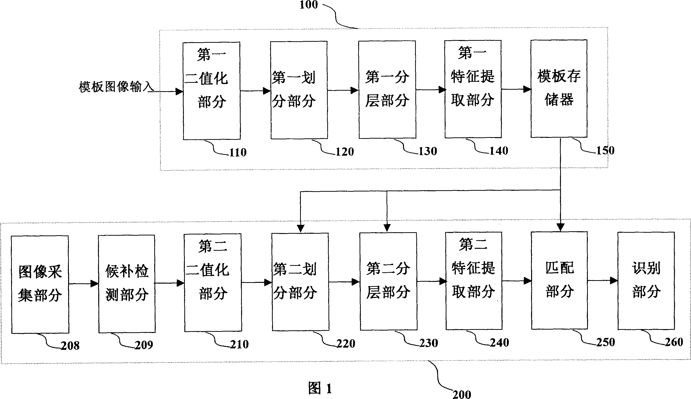
[0036] FIG. 1 shows a block diagram for explaining the constitution of an apparatus for recognizing an image according to a first embodiment of the present invention.

[0037] As can be seen from FIG. 1 , the image recognition device of the first embodiment has an offline part 100 and an online part 200 .

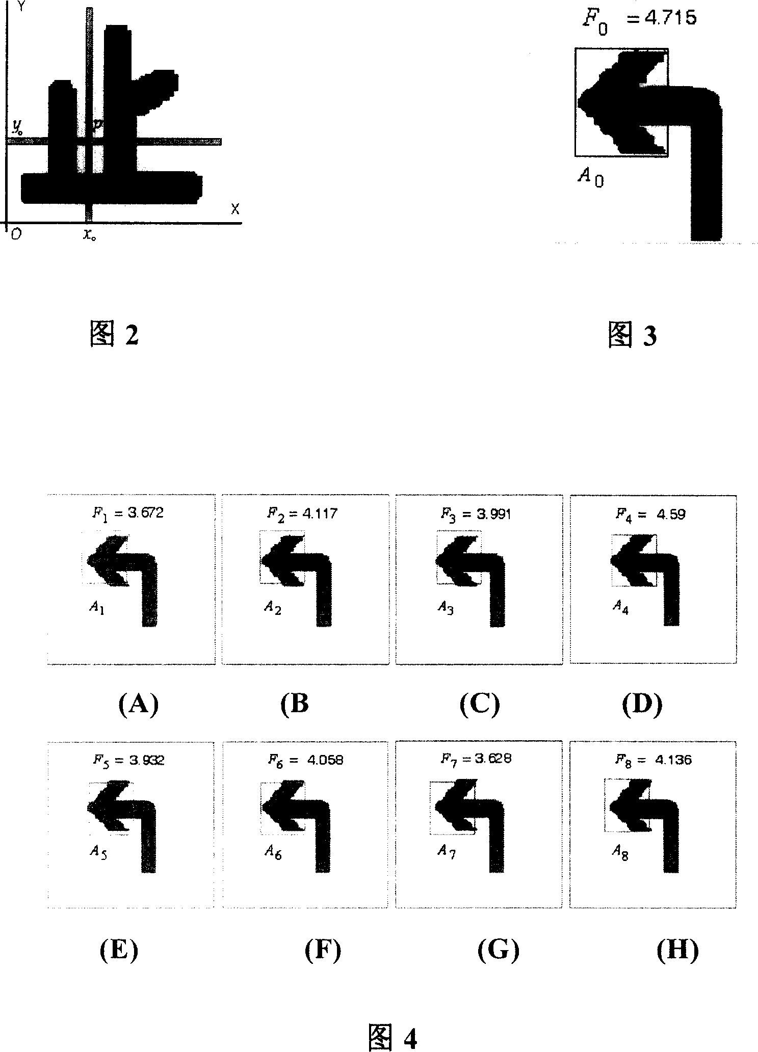
[0038] The offline part 100 includes a first binarization part 110 for binarizing the input template image, a first division part 120 for dividing the binary template image to obtain basic recognition units, and a first division part 120 for dividing the basic recognition units into layers. The first layering part 130, the first feature extraction part 140 for extracting the histogram feature information of each basic recognition unit and the relative geometric relationship between them, and the histogram information and the histogram information for each template image and its basic recognition unit The relative geometric relationship is correspondingly stored in the templ...

no. 2 approach

[0077] FIG. 11 shows a block diagram of an apparatus for recognizing images according to a second embodiment of the present invention.

[0078] It can be seen from FIG. 11 that the image recognition device of the second embodiment also has an offline part 100 and an online part 200 .

[0079] The offline part 100 includes extracting the edge of the input template image so as to obtain the first edge extraction part 310 of the edge template image, dividing the edge image template image to obtain the first division part 320 of the basic recognition unit, dividing the basic recognition unit into levels The first layering part 330, the first feature extraction part 340 for extracting the histogram information of each basic recognition unit and the relative geometric relationship between them, and the histogram information and the histogram information for each template image and its basic recognition unit The relative geometric relationship is correspondingly stored in the templat...

no. 3 approach

[0091] FIG. 14 shows a block diagram for explaining the structure of an apparatus for recognizing an image according to a third embodiment of the present invention.

[0092] It can be seen from FIG. 14 that the image recognition device of the third embodiment also has an offline part 100 and an online part 200 .

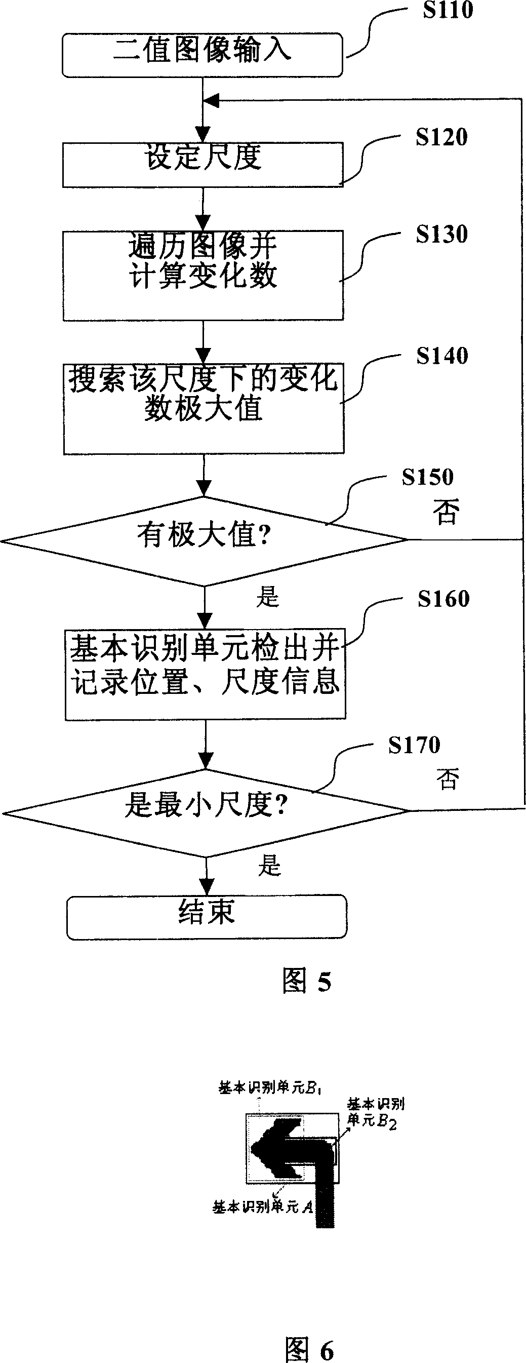
[0093] The offline part 100 includes a first division part 520 that divides the basic recognition unit of the template image by calculating the number of changes, a first main color analysis part 525 that analyzes the main color of each basic recognition unit, and a first main color analysis part that divides the basic recognition unit into layers. The layering part 530, the first feature extraction part 540 used to extract the histogram feature information of each basic recognition unit and the relative geometric relationship between them, and the histogram information and relative geometric relationship between each template image and its basic recognition unit The...


PUM


Abstract

The invention discloses a method and device for recognizing image, which comprises the following procedures: detect a candidate area in an input image; divide recognition unit in the candidate area based on a basic recognition unit in a template image; the basic recognition unit refers to a partial image with much variety in the template image; the recognition unit refers to a partial image corresponding to the basic recognition unit in the template image of the candidate area; calculate a bar graph information of the recognition and/or relative geometric relation to determine the similarity between partial or all of the bar graph and/or relative geometric relation and that of basic recognition unit of the template image; judge whether there is the image of the object described in the template image in the input image according to the similarity. Therefore, the invention can be adopted to improve the accuracy for image recognition.

Description

technical field [0001] The present invention relates to image processing technology, and in particular, the present invention relates to a method and device capable of identifying captured images with high accuracy. Background technique [0002] Image recognition technology is being used in more and more automated processes and has achieved significant performance improvements. The process of image recognition includes a series of steps of acquisition, detection, and identification. Due to the influence of the acquisition equipment and the acquisition environment, the input image to be identified may have greater interference, such as blurring, occlusion, shadows, lighting changes, etc., the target to be identified Images may be distorted or rotated. Therefore, how to identify targets efficiently and accurately is one of the key and difficult points to be studied in image recognition technology. [0003] In the image recognition application of some actual scenes, the detec...

Claims


Application Information

Patent Timeline
IPC IPC(8): G06K9/46G06T7/00G06V10/48
CPCG06T2207/30184G06T2207/30236G06T2207/30108G06K9/4633G06T7/0004G06T2207/10032G06V10/48
Inventor 谢晓辉刘伟杰吴刚魏强
Owner PANASONIC CORP
Why Eureka
Try Eureka