Detecting and control method for luminous module group

A technology of light-emitting module and control method, applied in the direction of cathode ray tube indicator, instrument, static indicator, etc., can solve the problems of flickering, human eye discomfort, discomfort and so on

Inactive Publication Date: 2008-01-23
GIGNO TECH CO LTD
View PDF0 Cites 6 Cited by
  • Summary
  • Abstract
  • Description
  • Claims
  • Application Information

AI Technical Summary

Problems solved by technology

However, when the light-emitting diode is turned off, it will inevitably cause flickering (Flicker) of the display screen, which makes the human eyes feel uncomfortable.
In addition, in addition to light-emitting diodes, any light-emitting unit or light-emitting module composed of light-emitting units that need to be adjusted in color balance will face the phenomenon of flicker when adjusting the color balance when using the existing conventional technology for adjustment. The problem
[0007] Therefore, how to provide a detection and control method for light emitting modules, which can improve the difference between each light emitting module, so that the electronic products used by the light emitting modules can obtain better color performance, At the same time, it can improve the flickering phenomenon of the display screen while adjusting the color balance, which makes the human eye feel uncomfortable.

Method used


Image

  • Detecting and control method for luminous module group
  • Detecting and control method for luminous module group
  • Detecting and control method for luminous module group

Examples


Embodiment Construction

[0045] In order to further explain the technical means and effects of the present invention to achieve the intended purpose of the invention, the specific implementation methods, methods, Steps, features and effects thereof are described in detail below.

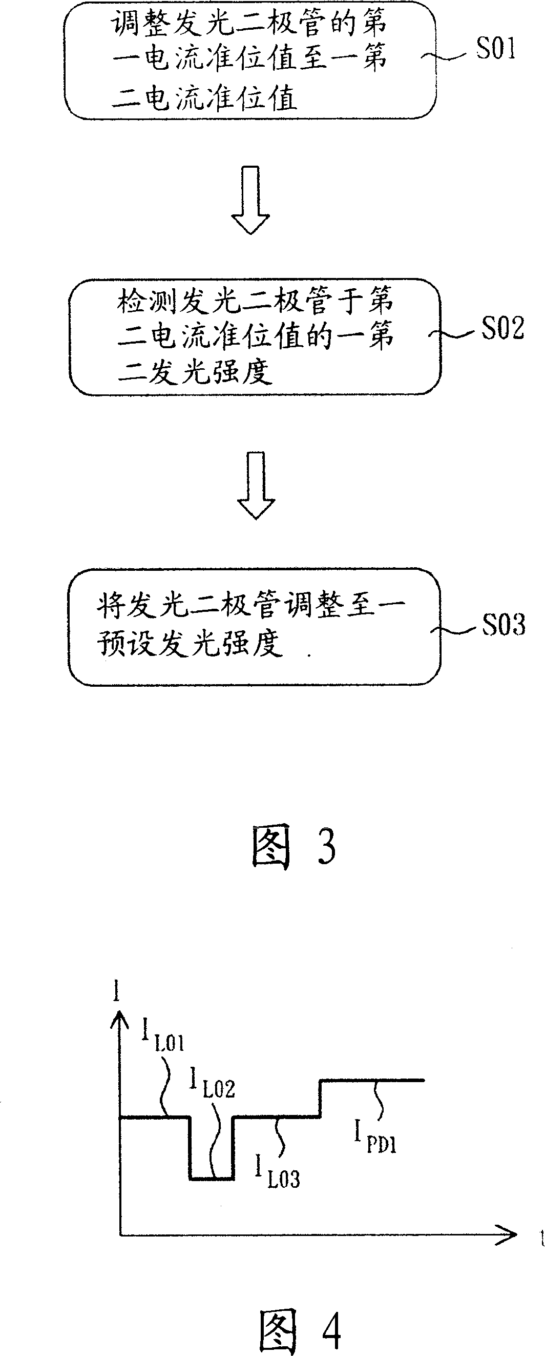
[0046] Please refer to FIG. 2 , which is a schematic diagram of hardware used in conjunction with the detection and control method of the light emitting module according to the first embodiment of the present invention. The hardware structure used in conjunction with the first embodiment of the present invention includes a light emitting module 21 , a light detection unit 22 , a current detection unit 23 , a control unit 24 and a drive unit 25 . In this embodiment, the light emitting module 21 is a light emitting diode as an example, which can be a white light emitting diode, a red light emitting diode, a blue light emitting diode or a green light emitting diode, of course the light emitting module 21 can also include A plu...


PUM


Abstract

The invention relates to a check and control method for an illuminant module, which is characterized in that: a first luminance intensity is positioned in a first current standard position value in the illuminant module. The check and control method comprises the following procedures: adjust the first current standard position value of the illuminant module to a second current standard position value, wherein, the absolute value of the first and the second current standard position exceeds zero; check a second luminance intensity of the second current standard position value in the illuminant module; adjust the illuminant module to a preset luminance intensity according to the first current standard position value, the first luminance intensity, the second current standard position value and the second luminance intensity. Therefore, the invention is able to reduce flickering display menu in adjusting the color balance of display device.

Description

technical field [0001] The invention relates to a detection and control method, in particular to a detection and control method of a light-emitting module capable of reducing flickering of a display screen when a display device adjusts color balance. Background technique [0002] In a liquid crystal display device, a cathode fluorescent lamp is generally used as a light emitting unit of a backlight source. However, since the color performance of cathode fluorescent lamps is inferior to that of light emitting diodes (LEDs), there are currently some manufacturers using light emitting diodes as backlight sources for liquid crystal display devices under the premise that the technology of light emitting diodes is gradually maturing. [0003] However, because light-emitting diodes will change and attenuate their luminous intensity due to changes in temperature and time, and the degree of attenuation of each light-emitting diode is different. Therefore, when light-emitting diodes a...

Claims


Application Information

Patent Timeline
Patent Type & Authority Applications(China)
IPC IPC(8): G09G3/36G09G3/34G09G3/20G09G5/02G09G5/10G02F1/133
Inventor 林峰立
Owner GIGNO TECH CO LTD
Why Eureka
Try Eureka