

Liquid crystal display device
a liquid crystal display and display device technology, applied in liquid crystal compositions, instruments, chemistry apparatus and processes, etc., can solve problems such as color shifting, lcds are not capable of solving problems, and the contrast ratio is changed with a viewing angle direction, so as to prevent color shifting and improve picture image quality
- Summary
- Abstract
- Description
- Claims
- Application Information
AI Technical Summary
Benefits of technology
Problems solved by technology
Method used
Image

Examples
first embodiment
[0039]Hereinafter, an in-plane switching mode liquid crystal display device according to the present invention will be described with reference to FIGS. 4 to 9.
[0040]Referring to FIGS. 4 and 5, a liquid crystal panel includes a TFT 55, a color filter layer 61, alignment layers 59, 62 over the first and second substrates 27, 26, respectively, a liquid crystal layer 60, and a spacer 65 between the first and second substrates 27, 26 to maintain a constant distance between the substrates 27, 26 and a polarizer on both surfaces of the liquid crystal panel.
[0041]In FIG. 4, the TFT 55 on the first substrate 27 is disposed at a region where a gate bus line 41 and data bus line 42 are crossed perpendicularly with each other. A common bus line 43 parallel to the gate bus line 41 is formed in the center of a pixel in a matrix form. A common electrode 49 connected to the common bus line 43 is formed in the pixel. A data electrode 48 connected to the drain electrode 47 of the TFT 55 is formed in...
second embodiment
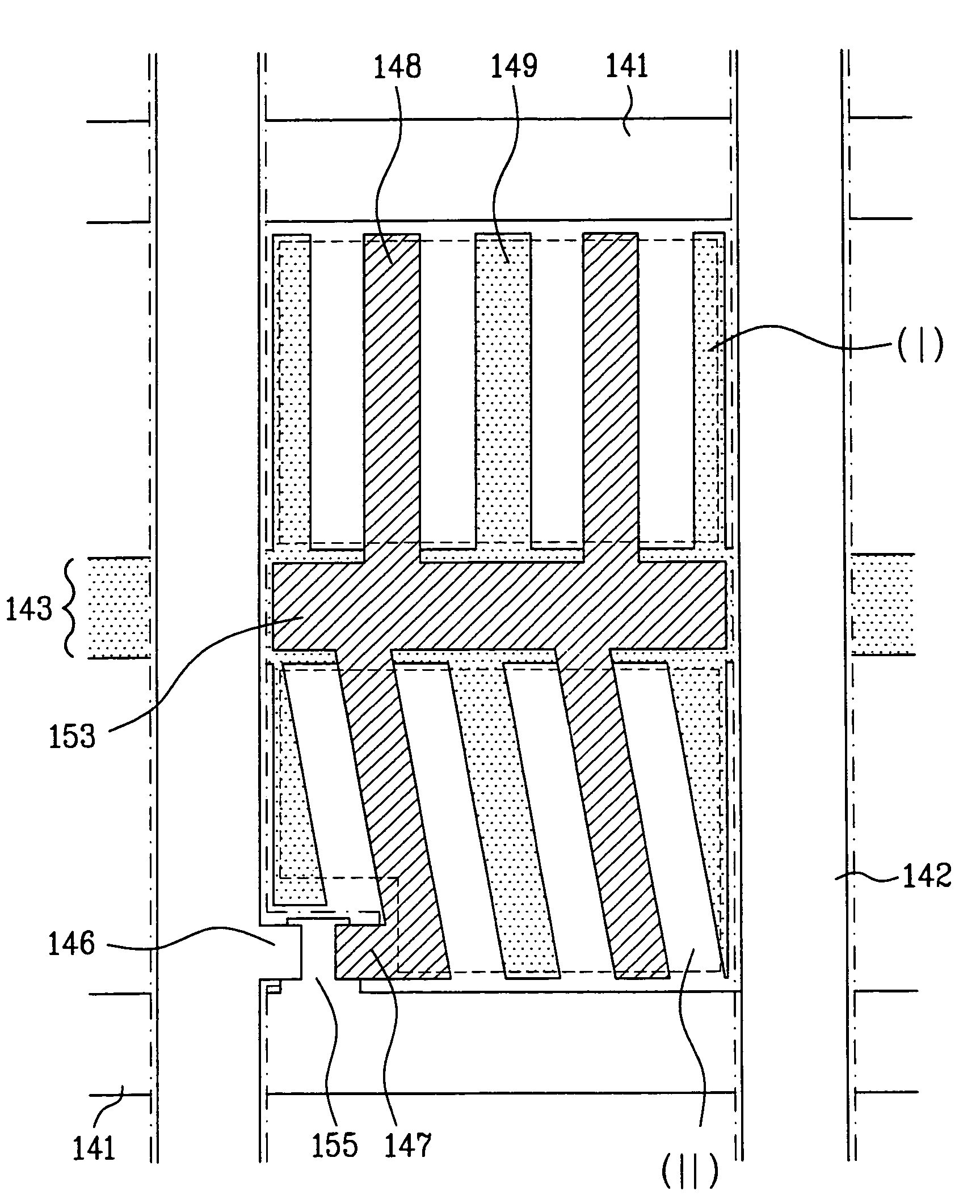
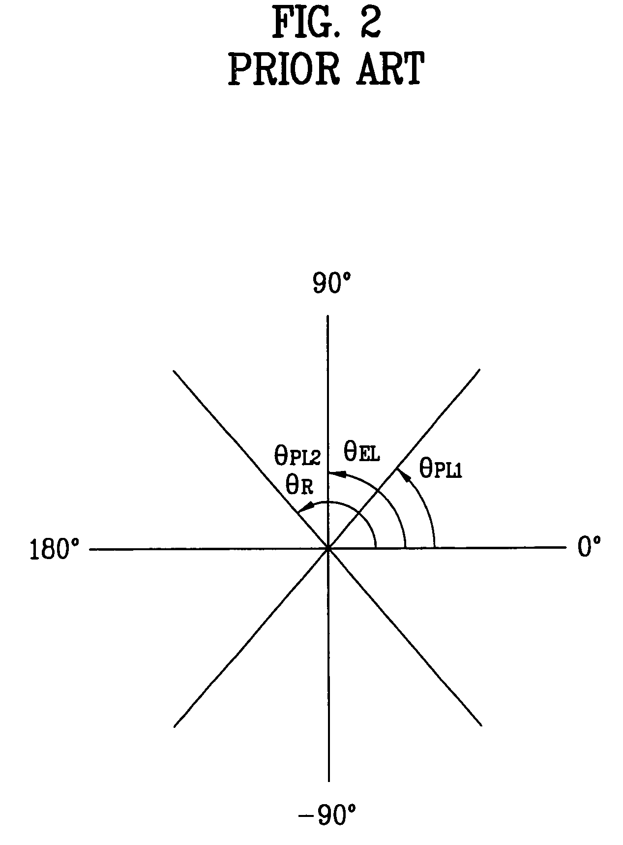
[0067]Referring to FIGS. 10 and 11, a second embodiment in the present invention will be described as following. As shown in the FIG. 10, the pixel is divided into a first region I and second region II. A common bus line 153 is formed between the regions I and II. A common electrode 148 in the second region II is connected to a source electrode 147 of the TFT. The common electrode 148 in the first region is elongated in the directions of θEL1=90° relative to longitudinal direction of the gate bus line 141 (i.e., 0° in FIG. 11) and 90°EL2R) in the alignment layer is relative to the longitudinal direction of the gate bus line 141. The angle θR of the rubbing direction in the alignment layer is larger than the angle θEL1 of the electrode elongation direction in the first region, and smaller than the angle θEL2 of the electrode elongation direction in the second region. Thus, the relationship among the angles of θEL1, θR, θEL2, is, θEL1REL2.
[0068]Therefore, the liquid crystal molecules ...
fourth embodiment
[0070]Referring to FIG. 14, a fourth embodiment will be described. The angles θEL1 and θEL2 of electrode elongation directions of the first region and the second region are 90° and between 90° and 180°, respectively, relative to the longitudinal direction of the gate bus line. First and second alignment layers have first and second alignment directions θR1 and θR2, respectively. The relationship between the alignment directions θR1 and θR2 is such that θEL1R1EL2 and θR2=180°−θEL1.
[0071]The rubbing process is to determine the alignment direction of the alignment layer in the each embodiments. The alignment direction may also be determined by irradiating the ultraviolet light into the alignment layer using the light alignment material as an alignment layer.
[0072]The present invention provides an in-plan switching mode liquid crystal display device that the pixel is divided into a plurality of regions. The data electrode and the common electrode of each region are symmetric relative to...
PUM
| Property | Measurement | Unit |
|---|---|---|
| thickness | aaaaa | aaaaa |
| thickness | aaaaa | aaaaa |
| thickness | aaaaa | aaaaa |
Abstract
Description
Claims
Application Information