
Meandering detection device, meandering detection method, meandering correction device, and image forming apparatus

Active Publication Date: 2008-05-15
KYOCERA DOCUMENT SOLUTIONS INC
View PDF3 Cites 4 Cited by
  • Summary
  • Abstract
  • Description
  • Claims
  • Application Information

AI Technical Summary

Benefits of technology

[0008]In view of the problem described above, the present invention has been made, and it is an object of the present invention to provide a meandering detection device, a meandering detection method, and a meandering correction device capable of detecting meandering of a subject with high accuracy. It is another object of the present invention to provide an image forming apparatus capable of preventing color shift.
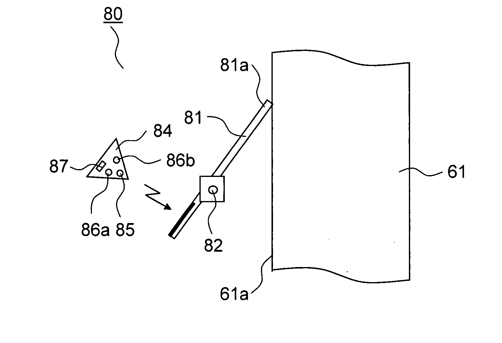
[0018]Consequently, even when the amount of light from the emission part varies depending on the ambient temperature, meandering of the subject can be detected with high accuracy based on a difference in the amount of light received between the first and second light receiving parts. Moreover, the contact of the meandering detection device is brought into contact with the side surface of the endless belt, which permits detecting meandering of the endless belt with high accuracy, thereby preventing color shift from occurring in the image forming apparatus.
[0020]Consequently, the emission part and the first and second light receiving parts can be easily installed apart from the endless belt. Moreover, toner adhesion to the emission part and the first and second light receiving parts can be reduced, thereby preventing deterioration in the detection accuracy.
[0022]According to this configuration, the shape of the side surface of the endless belt is previously stored in storage means. The contact repeatedly traces the side surface of the revolving endless belt and tilts in accordance with the shape of the side surface. The degree of tilt of the contact by the shape can be obtained by recognizing the position of the endless belt with another sensor or the like. Consequently, from the outputs of the first and second light receiving parts, the degree of tilt of the contact by the shape is corrected to thereby draw the amount of meandering, thus permitting prevention of erroneous meandering detection.
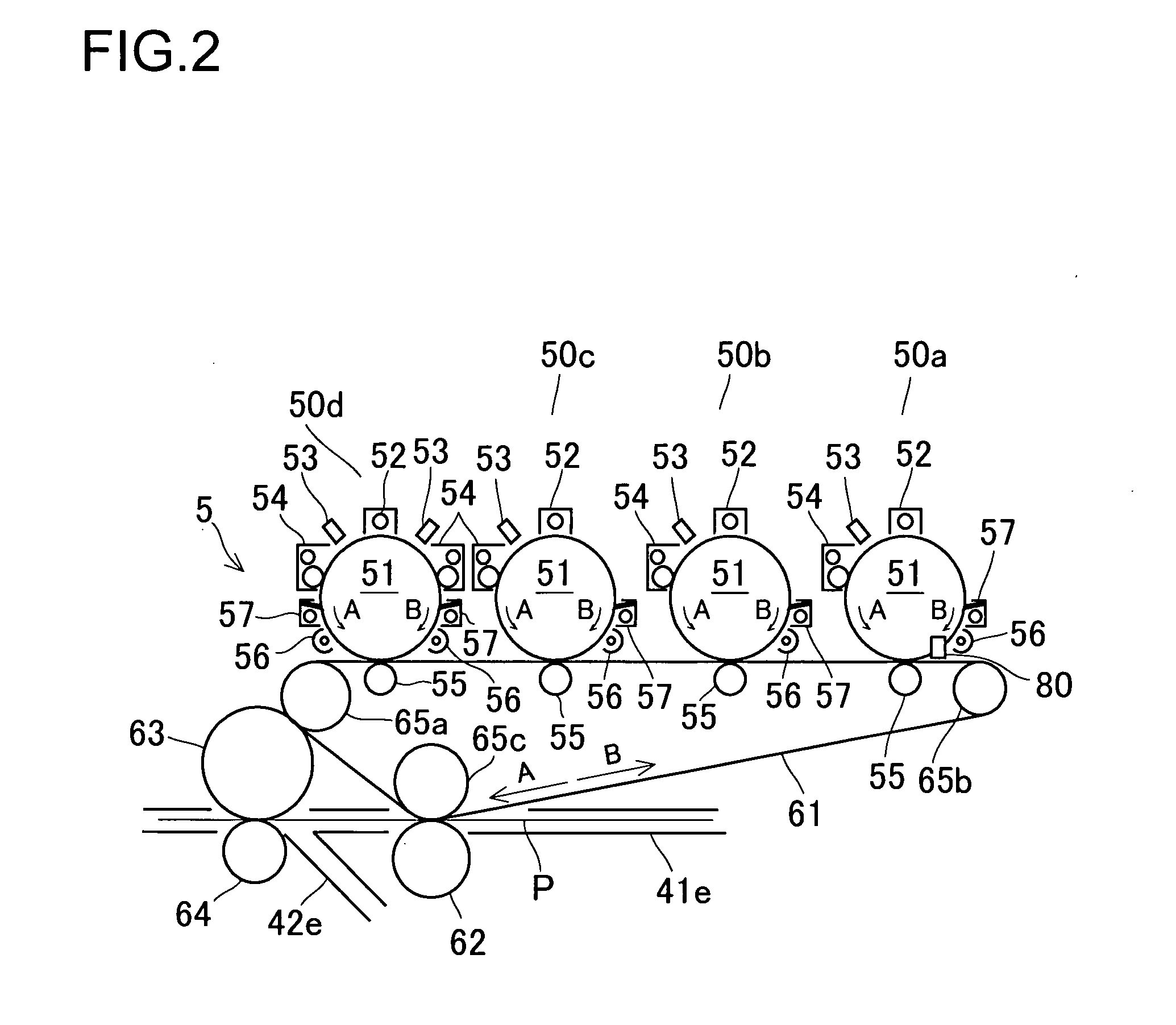
[0024]The image forming apparatus according to an eleventh aspect of the present invention, in the image forming apparatus according to the seventh aspect, based on a result of the detection by the meandering detection device, corrects a position of the endless belt in a direction perpendicular to a moving direction thereof. According to this configuration, upon detection of meandering of the endless belt by the meandering detection device, the running position of the endless belt is corrected in such a direction as to cancel the meandering of the endless belt, thus permitting easily providing an image forming apparatus without color shift.

Problems solved by technology

Thus, with the conventional meandering detection device described above, even when the endless belt is not meandering, an increase in the ambient temperature decreases the amount of light received by the light receiving element, thus resulting in erroneous detection that meandering is occurring.
This poses a problem of color shift occurring in the image forming apparatus.

Method used


Image

  • Meandering detection device, meandering detection method, meandering correction device, and image forming apparatus
  • Meandering detection device, meandering detection method, meandering correction device, and image forming apparatus
  • Meandering detection device, meandering detection method, meandering correction device, and image forming apparatus

Examples


Embodiment Construction

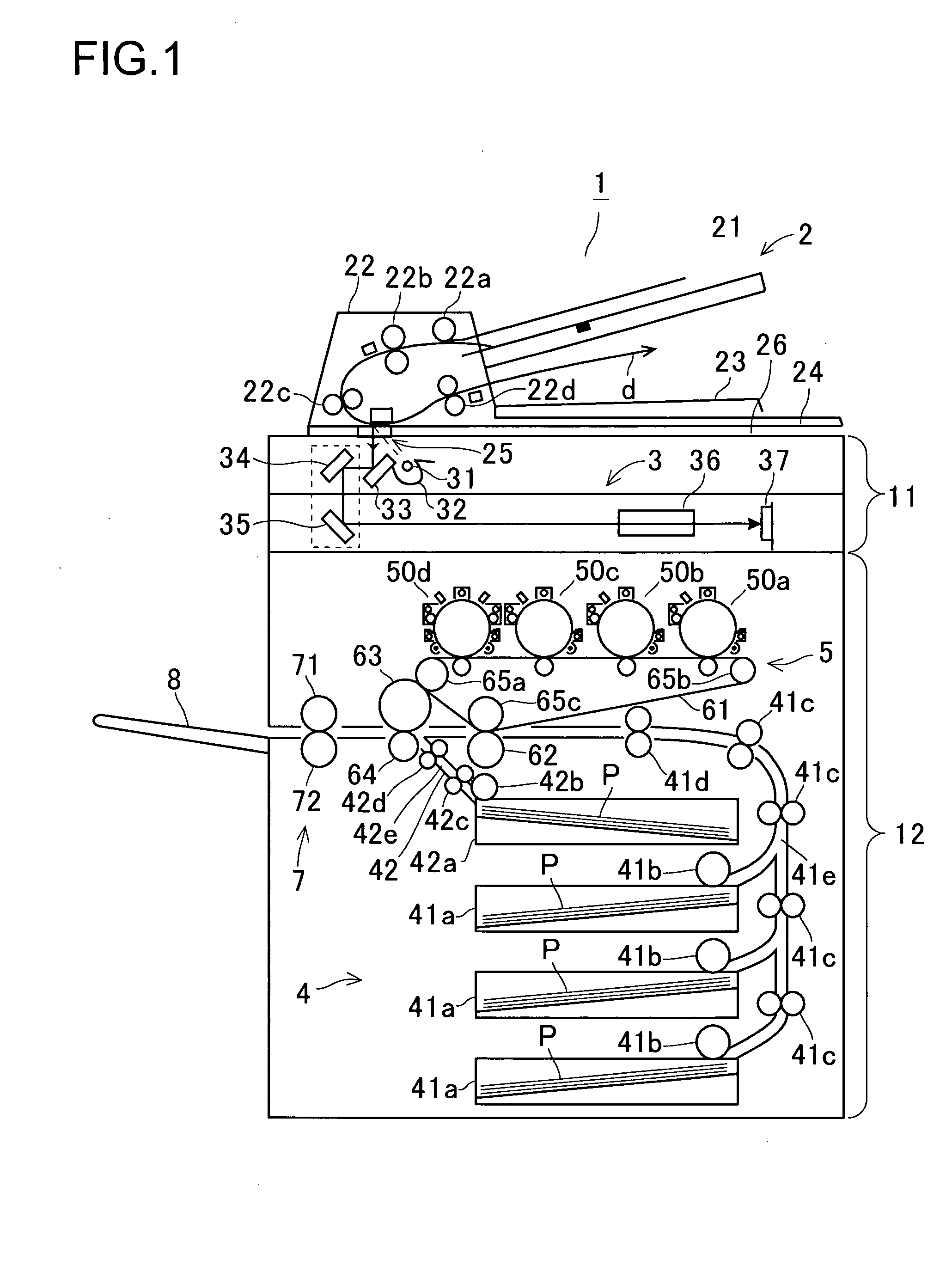
[0031]Hereinafter the embodiments of the present invention will be described with reference to the accompanying drawings. FIG. 1 is an elevation view to show a configuration of an image forming apparatus according to a first embodiment. The image forming apparatus 1 is a color copier, and has an upper housing 11 and a lower housing 12. On the upper housing 11, a document conveyance part 2 for conveying a document is mounted in such a manner as to be capable of opening and closing with a support provided at the rear part thereof.

[0032]The document conveyance part 2 includes: a document feed tray 21, a document conveyance part main body 22, a document discharge tray 23, and a document cover 24. On the document feed tray 21, a document is loaded. The document conveyance part main body 22 conveys the document fed from the document feed tray 21 for scanning. The document discharge tray 23 stores the document discharged from the document conveyance part main body 22. The document cover 24...


PUM


Abstract

A meandering detection device capable of detecting meandering of a subject with high accuracy includes: a contact which has an open end making contact with and following a subject body and which is supported by a support part; a reflection part integrally provided to the contact and reflecting light; an emission part emitting light toward the reflection part; and a first and a second light receiving parts which are disposed in front of the reflection part, which receive the light reflected by the reflection part and then outputs signals in accordance with respective amounts of light received, and which detect meandering of the subject based on a difference in the amount of light received.

Description

[0001]This application is based on Japanese Patent Application No. 2006-307897 filed on Nov. 14, 2006, the contents of which are hereby incorporated by reference.BACKGROUND OF THE INVENTION[0002]1. Field of the Invention[0003]The present invention relates to a meandering detection device and a meandering detection method for detecting meandering of a subject. The present invention also relates to a meandering correction device including the meandering detection device for detecting meandering of a subject. The present invention further relates to an image forming apparatus including the meandering detection device for detecting meandering of a revolving endless belt.[0004]2. Description of Related Arts[0005]An image forming apparatus including a conventional meandering detection device is disclosed in JP-A-H8-10623. This meandering detection device detects meandering of an endless belt that conveys a recording sheet of an image forming apparatus that is formed of a color copier, to ...

Claims


Application Information

Patent Timeline
IPC IPC(8): G01B11/14G03G15/00
CPCG03G15/50G03G15/1615G03G2215/00143
Inventor FUJIHARA, KENSUKE
Owner KYOCERA DOCUMENT SOLUTIONS INC
Learn More