Optical element

a technology of optical elements and antireflection films, applied in the field of optical elements, can solve the problems of poor adhesion of antireflection films, scratched outside air, and difficult glass work process, and achieve the effect of good environmental durability

Inactive Publication Date: 2006-05-04
NIKON CORP
View PDF11 Cites 79 Cited by
  • Summary
  • Abstract
  • Description
  • Claims
  • Application Information

AI Technical Summary

Benefits of technology

[0009] The present invention was devised in light of such circumstances, and the first object of the present invention is to provide an optical element which is formed by superimposing a plurality of resin layers on a matrix m

Problems solved by technology

However, in such an optical element, the surface of a matrix material such as a glass must be worked, so that there is encountered the problem that this process of working the glass requires effort.
Furthermore, the formation of the silane coupling treatment layers is not necessarily an es

Method used


Image

  • Optical element
  • Optical element
  • Optical element

Examples


embodiment 1

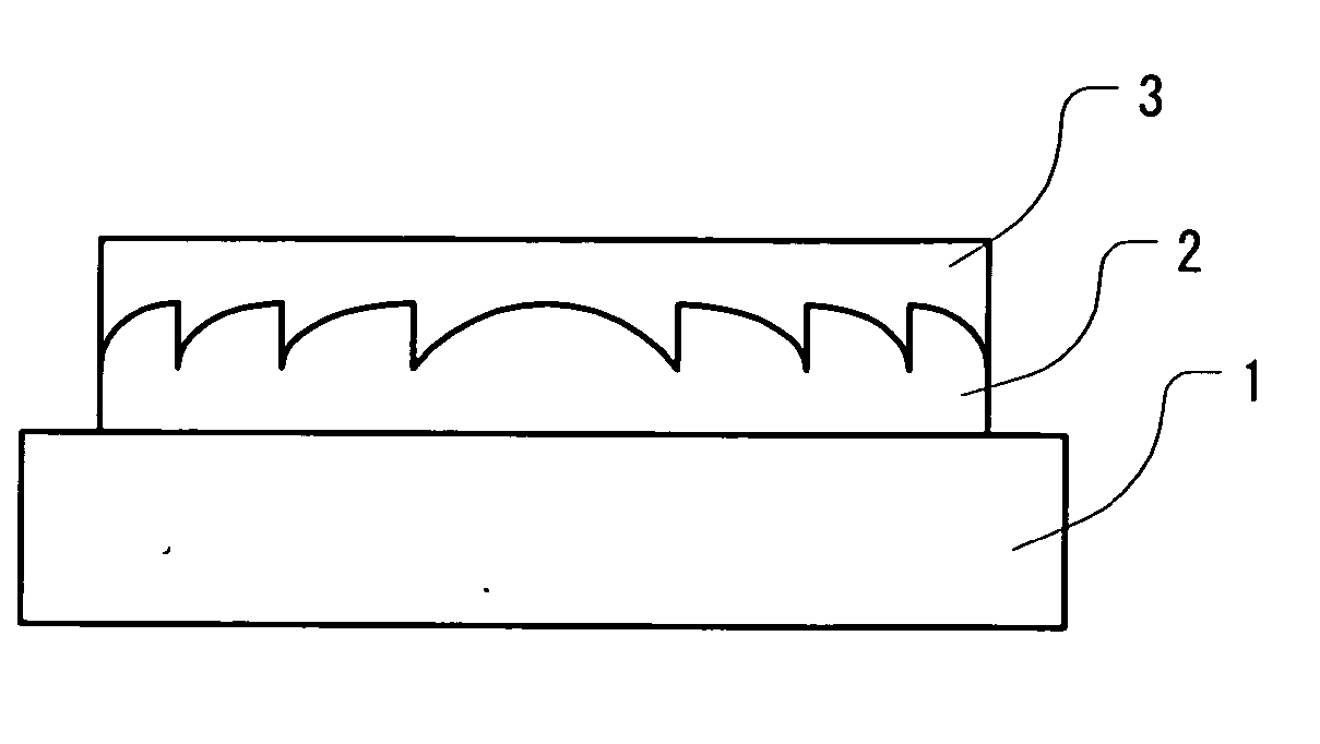
[0065] Optical elements having the shapes shown in FIG. 1 (diffractive lenses having the function of a convex lens) were formed. The external diameter of the optical elements (resin portion) was 60 mm, the diffraction grating was a circular shape, the pitch in the vicinity of the center of the lens was 2 mm, with this pitch becoming narrower toward the outer circumference as shown in FIG. 1, so that the pitch in the vicinity of the outer circumference was 0.12 mm.

[0066] A resin whose main component is urethane acrylate was used as the resin 2, and a resin containing fluorinated acrylate was used as the resin 3. The refractive index of the resin 2 is greater than the refractive index of the resin 3. The characteristics of the cured materials of the resin 2 and resin 3 are as shown in Table 1. In Table 1, variations in transmissivity before and after light resistance test by means of a carbon fade meter (abbreviated and described as “variations in transmissivity before and after carb...

embodiment 2

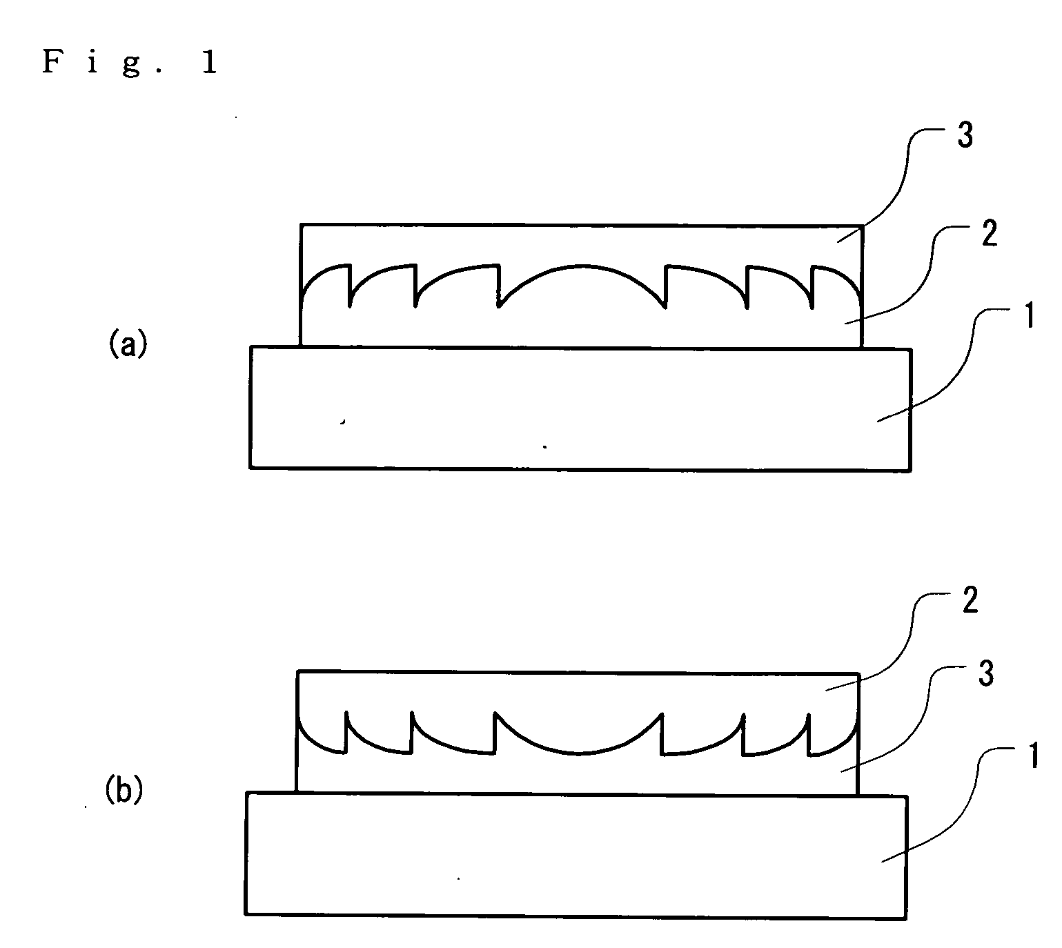
[0069] Diffractive lenses having a positive power were manufactured. The shape of the diffraction grating was a shape shown in FIG. 2(b), the external diameter of the optical elements was 60 mm, the height of the grating was 20 μm, and the grating pitch was 2 mm in the vicinity of the center and 0.12 mm in the vicinity of the outer circumference, so that the pitch was designed to be narrower toward the outer circumferential surface.

[0070] A resin whose main component is urethane acrylate was used as the high-refractive index resin 5, and a resin containing fluorinated acrylate was used as the low-refractive index resin 4.

[0071] In the first diffractive lens, no drafts were formed in the relief pattern, so that this lens had a vertical step structure. In the second diffractive lens, drafts were formed in the relief pattern as shown in FIG. 3, and these drafts were formed so that the inclination increased toward the edge portions of the diffractive lens, and the gradient at the oute...


PUM


Abstract

The complete vertical inversion of a combination of the resin layer 2 and resin layer 3 in (a) is (b). Accordingly, (a) and (b) have the same optical characteristics. Between the resin layer 2 and resin layer 3, the resin layer that is sandwiched between the substrate 1 and the uppermost resin layer (i.e., the resin layer 2 in (a) and the resin layer 3 in (b)) does not have its surface directly contacting the outside air, but the uppermost resin layer (i.e., the resin layer 3 in (a) and the resin layer 2 in (b)) has its surface contacting the outside air. Accordingly, after comparing the resin in the resin layer 2 and the resin in the resin layer 3 in terms of environmental durability, if the environmental durability of the resin in the resin layer 2 is superior to the environmental durability of the resin in the resin layer 3, the construction shown in (b) may be adopted, and if the environmental durability of the resin in the resin layer 3 is superior to the environmental durability of the resin in the resin layer 2, then the construction shown in (a) may be adopted.

Description

[0001] This is a continuation from PCT International Application No. PCT / JP2004 / 008822 filed on Jun. 17, 2004, which is hereby incorporated by reference.TECHNICAL FIELD [0002] The present invention relates to an optical element such as a diffractive lens that is provided with specified optical characteristics by laminating two or more layers of resins on a matrix material. BACKGROUND ART [0003] Optical elements have been publicly known in which a resin layer having a different refractive index from a matrix material such as a glass is formed on the surface of this matrix material, and the interface between this matrix material and the resin layer is formed into a particular shape, thus as a whole providing the characteristics of an optical element such as a diffractive lens. However, in such an optical element, the surface of a matrix material such as a glass must be worked, so that there is encountered the problem that this process of working the glass requires effort. [0004] As an...

Claims


Application Information

Patent Timeline
IPC IPC(8): B32B3/00B29D11/00G02B3/08G02B5/18
CPCB29D11/0073G02B3/08Y10T428/24612G02B27/0018G02B5/1814
Inventor MIYAKAWA, AKIKONAKAMURA, TORU
Owner NIKON CORP
Why Eureka
Try Eureka