Image forming apparatus, optical scanning control method, optical scanning control program and recording medium

A control method and optical scanning technology, which are applied in the fields of image forming apparatuses and copiers, and can solve the problems of not considering the elimination of color shift and the like

Inactive Publication Date: 2009-09-23
RICOH KK
View PDF1 Cites 5 Cited by
  • Summary
  • Abstract
  • Description
  • Claims
  • Application Information

AI Technical Summary

Problems solved by technology

[0007] In this way, in the conventional technology, a method called surface jump control is used t

Method used


Image

  • Image forming apparatus, optical scanning control method, optical scanning control program and recording medium
  • Image forming apparatus, optical scanning control method, optical scanning control program and recording medium
  • Image forming apparatus, optical scanning control method, optical scanning control program and recording medium

Examples


no. 1 example

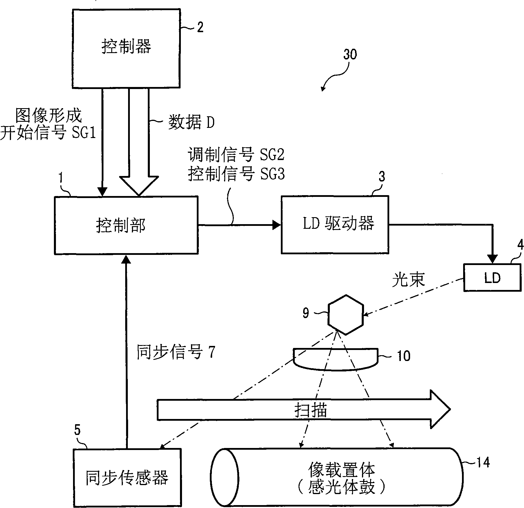
[0092] figure 1 A control configuration diagram showing the light scanning device portion of the image forming apparatus according to the first embodiment of the present invention. In this figure, the control structure of the optical scanning device is composed of a controller 2 , an LD driver 3 , an LD 4 , a synchronization sensor 5 , a polygon mirror 9 , and an optical component 10 centered on the control unit 1 . The control unit 1 is constituted by a CPU or its peripheral ASIS. The control unit 1 receives the start signal SG1 and the data D from the controller 2 , modulates the image data at a preset time, for example, for every line or multiple lines, and transmits it to the LD driver 3 . The LD driver 3 drives the LD4 according to the transmitted image forming signal (modulation signal) SG2. In addition, the control signal SG3 including the LDON signal is output from the control unit 1 to the LD driver 3 . The polygon mirror motor drives the polygon mirror 9 as a rev...

no. 2 example

[0124] Figure 7 is a block diagram showing the control structure of the optical scanning device according to the second embodiment, Figure 8 It is a time chart showing the control time of the second embodiment. The second embodiment is provided with mediation means, and when a multi-color image is formed at a slower speed than normal without changing the rotational speed of the rotating polyhedron during writing, by changing the lighting time according to the synchronizing signal, the multiple surfaces of the rotating polyhedron are changed. The synchronization signal can be obtained once, and the change period of the lighting time according to the synchronization signal can be mediated between each color.

[0125] Specifically, the synchronization control unit 6 of the first embodiment is replaced by a half-speed switching signal generating unit 8 , and the synchronous lighting position is controlled by the half-speed switching signal generating unit 8 . That is, in the s...

no. 3 example

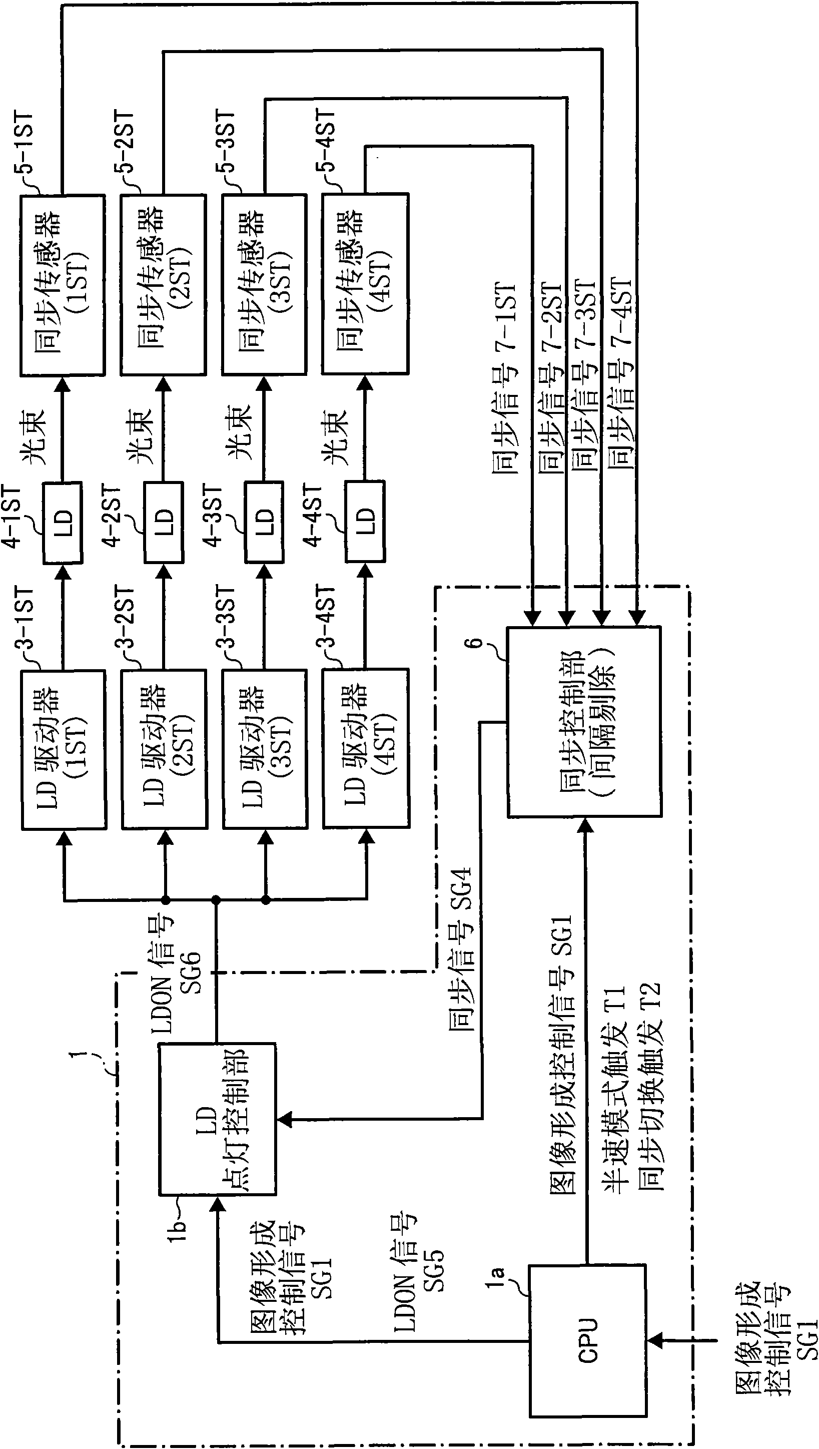
[0137] Figure 9 It is a block diagram showing the control structure of the optical scanning device of the third embodiment. This third embodiment is related to Figure 7 Compared to the second embodiment shown, it differs in the following respects:

[0138] 1) The synchronizing signals 7-1ST, 2ST, 3ST, and 4ST are input only to the half-speed switching signal generation unit 8, and are not input to the LD lighting control unit 1b.

[0139] 2) Replace the first to fourth LDs with two LDs respectively 1 , LD 2 , set to multi-beam.

[0140] 3) The ON / OFF of the lighting of the LD4 is controlled by the LDON / OFF signal SG9 from the LD lighting control unit 1b.

[0141] In this way, the LDON / OFF signal SG9 output from the LD lighting control unit 1b can be written in the half-speed mode without changing the rotational speed of the mirror motor. For this, refer to Figure 9 It can be seen that LD4 uses 8 LDs, that is, for each color, the first and second LDs are used 1 , LD ...


PUM


Abstract

The invention relates to an image forming apparatus, an optical scanning control method, an optical scanning control program and a recording medium. The image forming apparatus is capable of forming multi-color images, and is equipped with an optical scanning device comprising a polygon mirror and a plurality of synchronous sensors (5). The lighting control of LD (4) is carried out by a CPU (1a), a lighting control portion (1b), and a LD driver (3), the polygon mirror deflects a plurality of light beams emergent from the LD (4) for scanning, and the light beam deflected by the polygon mirror is transmitted to a plurality of synchronous sensors (5) to output a synchronous signal (7-ST). The polygon mirror is driven in the regular speed. When the multi-color image is formed in a speed lower than the regular speed, a synchronous signal (SG4) is generated for removing one time in a determined interval in the same time by a synchronization portion (6) using a plurality of synchronous signals (7) output from a plurality of synchronous sensors (5), and the control portion (1) forms image according to the synchronous signal. Even a face shifting control is executed, sub-scanning direction will not deviate.

Description

technical field [0001] The present invention relates to image forming apparatuses such as copiers, printers, facsimile machines, and digital multi-functional peripherals incorporating the above-mentioned functions, which are provided with an optical scanning device that performs optical writing using a revolving polyhedron, and an optical scanning device and an optical scanning device implemented by the above-mentioned optical scanning device and the image forming apparatus. A scanning control method, a light scanning control program for a computer to implement the light scanning control method, and a recording medium recording the light scanning control program. Background technique [0002] As such a technique, the invention disclosed in Patent Document 1 is known. The invention includes: a photoreceptor whose surface moves in a certain direction; a laser beam output means for outputting a laser beam modulated according to an image signal; The surface of the photoreceptor...

Claims


Application Information

Patent Timeline
IPC IPC(8): G03G15/01G02B26/12G03G15/04B41J2/447B41J2/47
CPCG03G2215/0404G03G15/326H04N1/506G03G15/0435
Inventor 赤松秀典
Owner RICOH KK
Why Eureka
Try Eureka