
Optical projecting system with color drum

A technology of optical projection and the use of color drums, applied in the field of optical projection systems, can solve the problems of inability to provide, structural limitations, complex optical systems, etc.

Inactive Publication Date: 2003-06-18
LG ELECTRONICS INC
View PDF0 Cites 5 Cited by
  • Summary
  • Abstract
  • Description
  • Claims
  • Application Information

AI Technical Summary

Problems solved by technology

However, the optical system adopted by this method is complex, which reduces the reliability, and basically cannot provide high light efficiency due to its structural limitations.

Method used


Image

  • Optical projecting system with color drum
  • Optical projecting system with color drum
  • Optical projecting system with color drum

Examples


Embodiment Construction

[0032] Preferred embodiments of the invention will now be described in detail, examples of which are illustrated in the accompanying drawings. Wherever possible, the same reference numbers are used throughout the drawings to apply to the same or like parts.

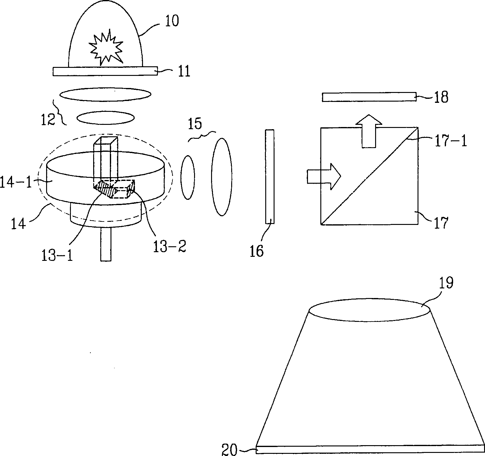
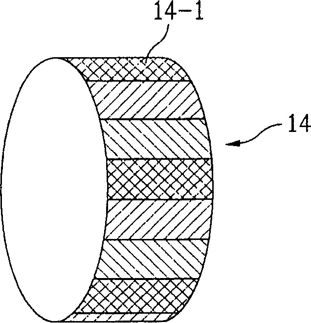
[0033] The present invention is characterized in that a plurality of color bands are determined such that the angle from one end to the other end of the light projection surface in the color drum does not exceed 30°, thereby preventing color shift. Therefore, the present invention can simply and conveniently provide an optical projection system using a color drum.

[0034] The optimal number of color bands depends on the size of the light projection surface, the position of the light projection surface, the characteristics of the optical system, and the structure of the optical system. The present invention can provide a color drum rolling optical system comprising at least six color ribbons.

[0035] That is, in the op...


PUM


Abstract

Disclosed is an optical projection system having a simple structure by scrolling a light of each wavelength efficiently on a panel by preventing a color shift by adjusting a width of a color band on a color drum surface properly. The present invention includes the color drum outputting an incident light through a predetermined number of color bands on a drum plane to display wherein a light outputted from an end of a light projecting plane outputting the incident light has an incident angle equal to or smaller than 30 DEG on the color band. Therefore, the present invention minimizes the influence of the color shift, provides an incident light in the scroll optical system effectively using the simple and inexpensive color drum, and prevents the degradation of image.

Description

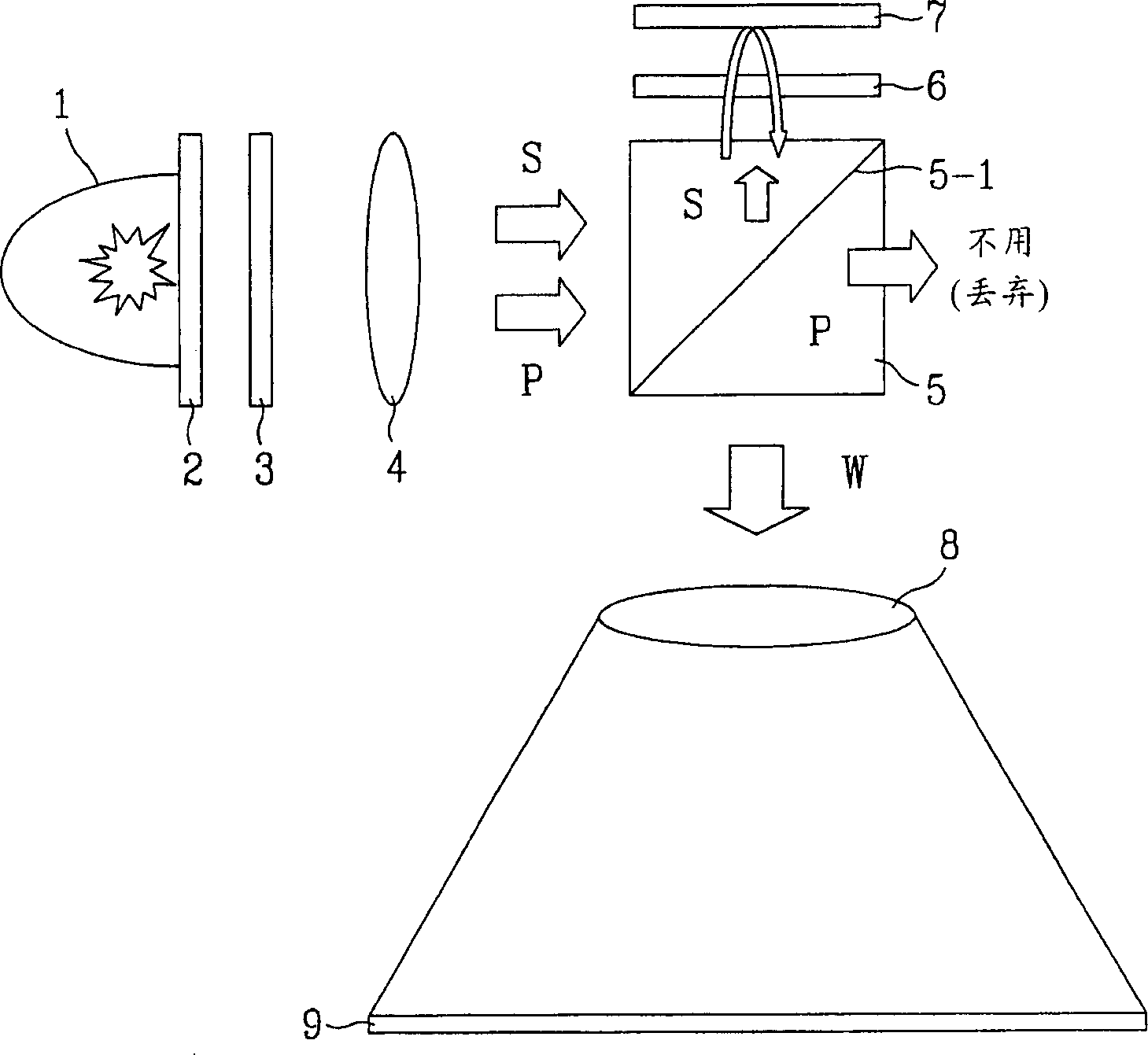
[0001] This application claims the benefit of Korean Application No. P2001-75457 filed on November 30, 2001, which is incorporated herein by reference. technical field [0002] The present application relates to an optical projection system using a color drum. Background technique [0003] Recently, with the hype of satellite and digital broadcasting, demand and interest in high-resolution widescreen displays has increased. Therefore, the prospect and task of projection / projector becomes very important. In addition, image information of high luminance and multi-color is strongly required as well as high resolution, and thus efforts are made to research and develop an optical system having high light efficiency and low price. [0004] Products of the related art generally use a three-screen system, thereby increasing product costs. So try to use a single screen system. [0005] figure 1 A structural diagram of a single-screen optical projection system according to the rel...

Claims


Application Information

Patent Timeline
IPC IPC(8): G02F1/13G02B27/18G02B27/28G03B21/14H04N9/31
CPCH04N9/3197H04N9/3117H04N9/31
Inventor 尹钟根
Owner LG ELECTRONICS INC
Learn More