

Guide plate used in side air bag
A guide plate and side airbag technology, applied in the field of guide plates, can solve problems such as impossible replacement of guide plates, contact, and difficulty in protecting occupants
- Summary
- Abstract
- Description
- Claims
- Application Information
AI Technical Summary
Problems solved by technology
Method used
Image

Examples
no. 1 example
[0084] A configuration of a guide plate for a side airbag according to a first embodiment of the present invention will be described hereinafter with reference to FIGS. 4 to 6 .
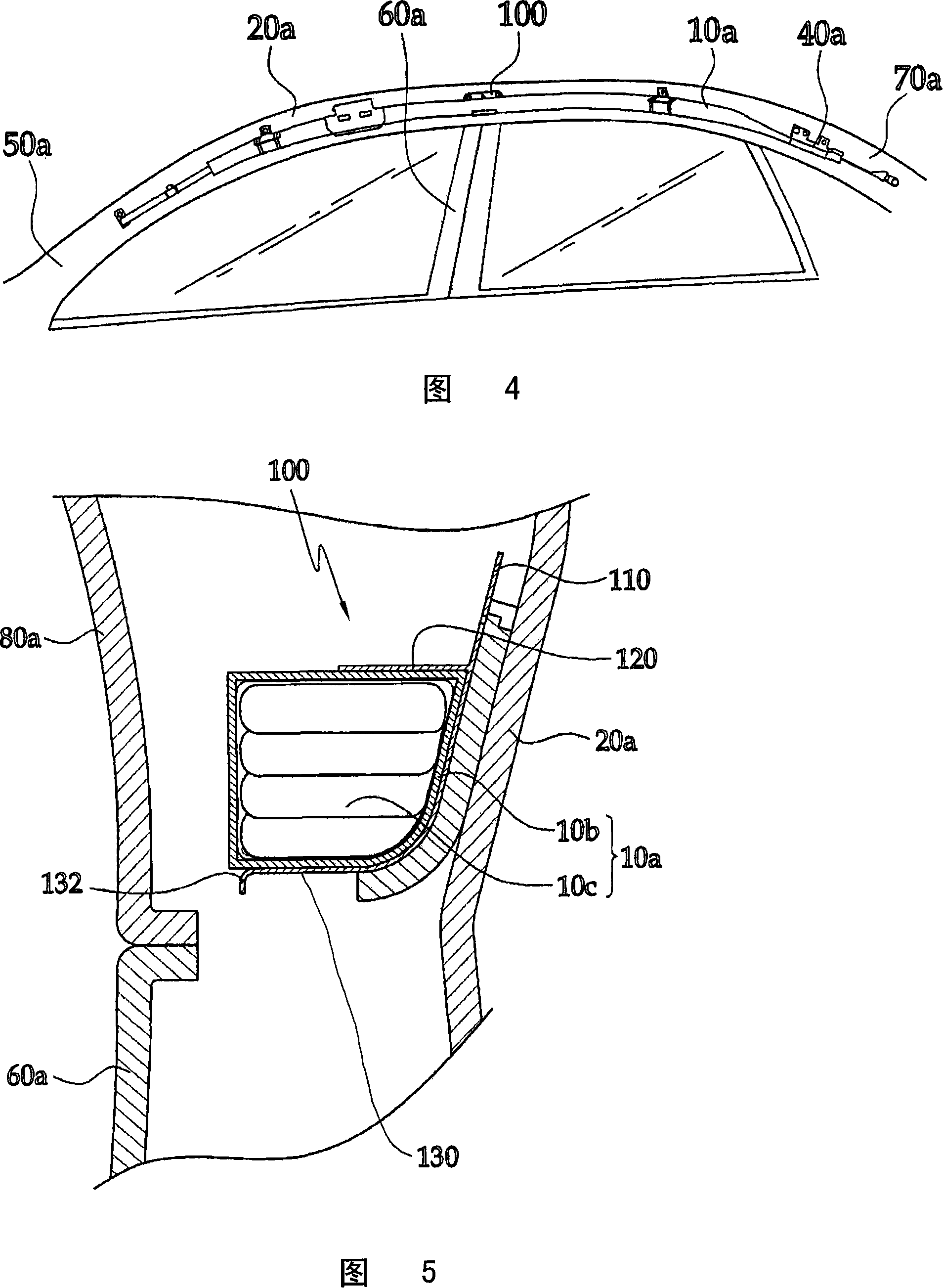
[0085] Referring to FIG. 4, the side airbag 10a is installed in the roof side panel 20a. The side airbag 10a has a front end secured to the front pillar 50a by a buckle and a rear end having the inflator 40a and connected to the rear pillar 70a.
[0086] The guide plate 100 according to the present invention is installed on the top side plate 20a above the center pillar 60a. The side airbag housing 10 b is fitted between the holding member 120 and the supporting member 130 of the guide plate 100 .
[0087] Although not shown in the drawings, the side airbag 10a includes a sensor for sensing a collision of the vehicle and an electronic control unit for operating the inflator 40a in response to a signal from the sensor.
[0088] 5 and 6 illustrate in detail a guide plate for a side airbag and an inst...
no. 2 example
[0106] 7(a) to 7(c) illustrate the configuration of a guide plate according to a second embodiment of the present invention.
[0107] Referring to FIG. 7( a), the holding member 120 protruding from the surface of the fixing member 110 has an extended holding member 121 which is separately and integrally formed at both longitudinal ends of the holding member 120 to prevent force Expand in the upward direction.
[0108] Referring to FIG. 7(b), the support member 130 has extension members 131 which are separately and integrally formed at both longitudinal ends of the support member 130 to prevent it from interfering with the center pillar 60a when the side airbag 10a is deployed.
[0109] Referring to FIG. 7( c ), an engagement member 122 is formed on the distal end of the holding member 120 to be bent in a downward direction. The engagement member 122 securely holds the side airbag housing 10b and causes the side airbag tube 10c to expand reliably toward the head liner 80a when...
no. 3 example
[0112] A guide plate for a side airbag according to a third embodiment of the present invention will be described below with reference to FIGS. 9 to 12 .
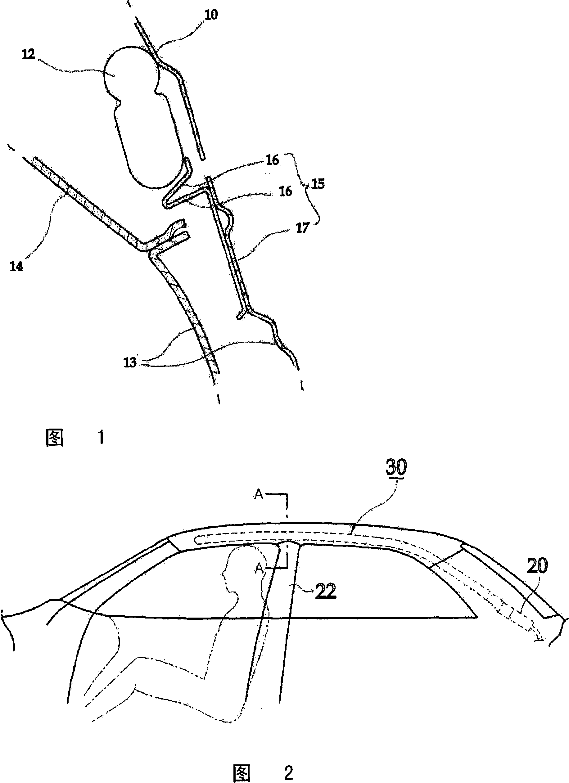
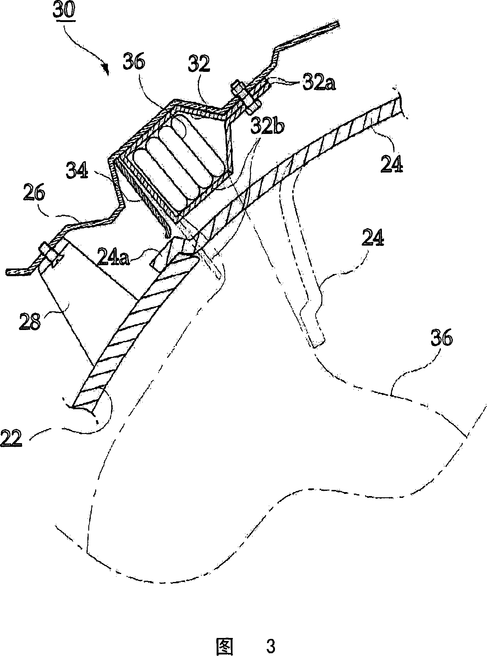
[0113] Referring to FIG. 11 , a side airbag 30 is installed facing a passenger space of a vehicle to protect occupants from injury. The side airbag 30 includes an airbag tube 36 folded multiple times, an airbag case 32 for receiving the airbag tube 36 , and an inflator connected to an end of the airbag tube 36 to inject high-pressure gas into the airbag tube 36 .
[0114] The airbag housing 32 has a door 32b on one side wall thereof, and has a mounting portion (not shown) at its upper end, which is bolted to the inner panel 26 . Each guide plate 200 is installed on the airbag case 32 at a predetermined position to support the lower surface of the airbag case 32 (see FIG. 12 ).
[0115] Referring to FIGS. 9 and 12 , the guide plate 200 is used for the side airbag 30 to support the lower surface of the airbag case 32 of the ...
PUM
 Abstract
Description
Claims
Application Information