
Device for fastening an object on a support plate and obtained assembly

a technology for fastening devices and objects, applied in the direction of wing fasteners, snap-action fasteners, fastening means, etc., can solve the problems of difficult assembly, large number of parts, complex manufacturing, etc., and achieve the effect of convenient manufacture, assembly and us

Inactive Publication Date: 2016-12-08
A RAYMOND & CO
View PDF0 Cites 6 Cited by
  • Summary
  • Abstract
  • Description
  • Claims
  • Application Information

AI Technical Summary

Benefits of technology

The invention provides two fastener systems that allow for secure fastening of a slider to a hollow body and prevent additional longitudinal engagement. It also allows for easy removal of the slider and detection of impact, which can then be addressed. Additionally, the invention includes a flexible finger to prevent cam finger insertion and a flap that prevents unfolding of the jaw branches during use.

Problems solved by technology

Such fastener devices present several major drawbacks.
Firstly, they require a large number of parts and they are complex to manufacture.
They are tricky to assemble, it being necessary to hold the spring in place in the hollow body before the slider is engaged and at the start of its engagement.
Secondly, each of such fastener devices requires longitudinal functional clearance to exist between the article and the support plate once locking has occurred.
If such longitudinal functional clearance does not exist, unlocking cannot be obtained without breaking one or more of the parts of the fastener device.
As a result of the longitudinal functional clearance, the article may inadvertently be moved closer to the plate and may cause the slider to be unlocked accidentally.
Furthermore, longitudinal functional clearance can give a user the feeling that the fastening is not secure since the user observes that the article can move, e.g. when it is subjected to vibration associated with variations in speed and unevenness in the road.
Finally, such devices do not make it possible to reveal a failed attempt at tearing out that has not resulted in separating the article, but that might have weakened the mechanical strength of the parts.

Method used


Image

  • Device for fastening an object on a support plate and obtained assembly
  • Device for fastening an object on a support plate and obtained assembly
  • Device for fastening an object on a support plate and obtained assembly

Examples


Embodiment Construction

[0036]The fastener device of the invention is for fastening an article on a support, e.g. a support plate or any other similar type of support. By way of example, the fastener device thus enables an article to be fastened inside the passenger compartment of a motor vehicle, or enables any other type of fastening.

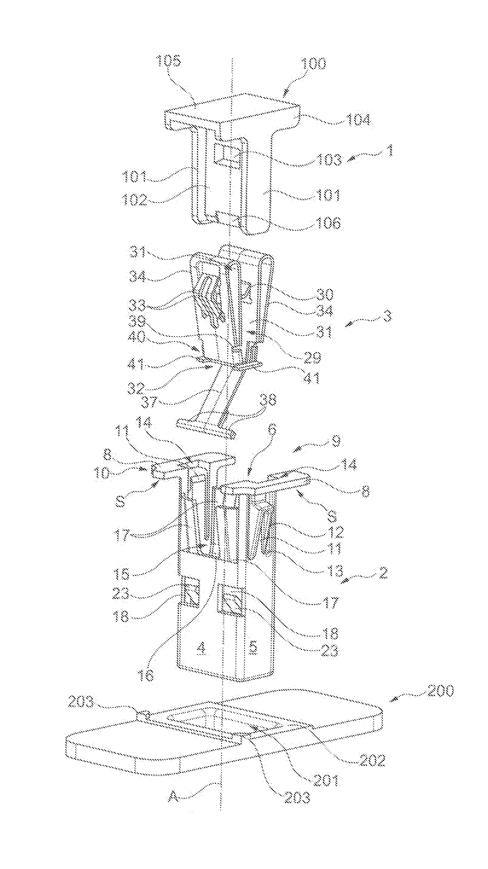
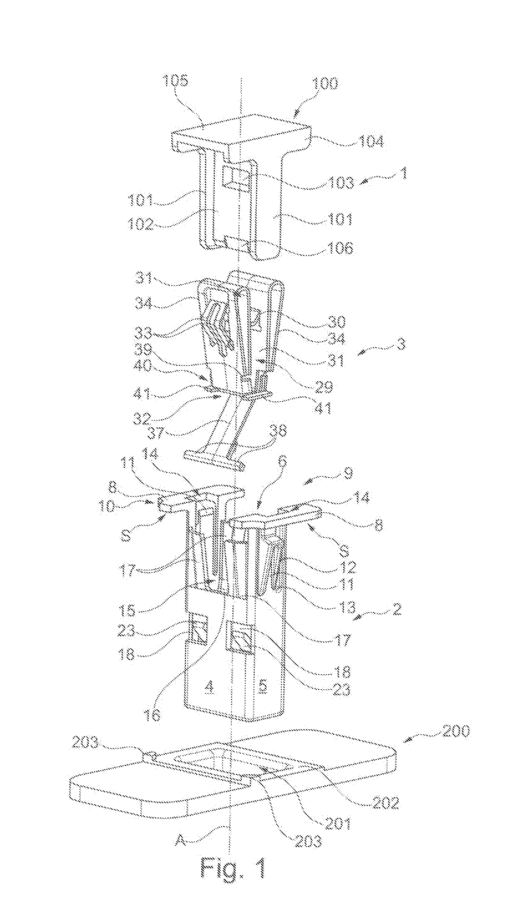
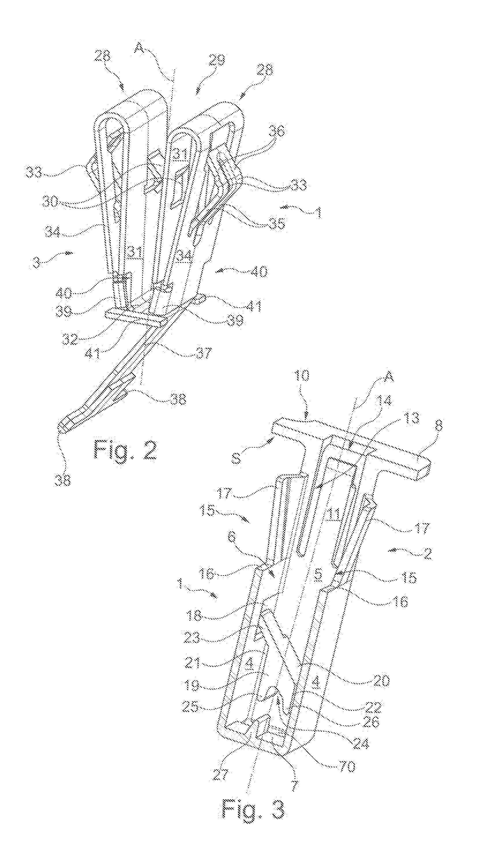
[0037]In the embodiment shown in particular in FIG. 1, the fastener device 1 is used to fasten an article 100 on a support plate 200. In this embodiment, the article 100 presents a double-T shape having stems 101 that are interconnected via a central slab 102 through which a slot 103 passes, and having branches 104 that are interconnected via a transverse slab 105 that co-operates with the branches 104 to form a head. The free end of the central slab 102 includes a beveled shape 106 for making it easier to fasten the article 100. By way of example, the article 100 is an intermediate part that is used to fasten another element (not shown). The support plate 200 includes an en...


PUM


Abstract

A fastener device for fastening an article on a support plate, and the resulting assembly, which fastener device comprises: a hollow body that is secured to the support plate; a slider that is secured to the article and that is suitable for being engaged in the hollow body; and blocking means.The blocking means comprise both at least one side opening that passes through the hollow body and also an elastically-deformable blocking tab that is carried by the slider and that, during engagement of the slider in the hollow body, is for deploying sideways into the side opening and for bearing simultaneously beneath the support plate so as to oppose any longitudinal removal of the slider, and against the slider so as to oppose any longitudinal thrust of the slider, and thus define a first blocking position.

Description

TECHNICAL FIELD[0001]The invention generally relates to a fastener device for fastening an article on a support plate, e.g. for fastening an article in the passenger compartment of a motor vehicle. The invention also relates to an assembly obtained with such a fastener device.PRIOR ART[0002]That type of fastener device should guarantee effective anchoring, in particular making it possible to withstand a head-on impact so as to avoid the article and / or the fastener device transforming into a projectile. In order to allow for maintenance, the fastener device should also be easy to undo.[0003]Publication FR 2 852 996 describes such a fastener device comprising a hollow body that is suitable for being secured to a support plate, and a slider that is suitable for being secured to the article to be fastened and housed in the hollow body. The hollow body and the slider are provided with blocking means that are suitable for longitudinally blocking the slider in the hollow body after a first...

Claims


Application Information

Patent Timeline
IPC IPC(8): F16B21/06
CPCF16B21/065E05C19/022E05C19/06
Inventor PQUET, JEROME
Owner A RAYMOND & CO
Learn More