Rail traveling type beam moving stillage truck

A rail-type, horizontally moving trolley technology, which is applied to bridges, bridge construction, erection/assembly of bridges, etc., can solve problems such as poor synchronization and safety, inconvenient operation, and high labor intensity, and achieve low pipeline requirements , low labor intensity and high degree of automation

Inactive Publication Date: 2008-02-06
湖南五新智能科技股份有限公司
View PDF0 Cites 12 Cited by
  • Summary
  • Abstract
  • Description
  • Claims
  • Application Information

AI Technical Summary

Problems solved by technology

Its shortcomings are large volume, high cost, inconvenient operation, especially poor synchronization and safety, low production efficiency, and high labor intensity. , the trolley will tilt, and ...

Method used


Image

  • Rail traveling type beam moving stillage truck
  • Rail traveling type beam moving stillage truck
  • Rail traveling type beam moving stillage truck

Examples


Embodiment Construction

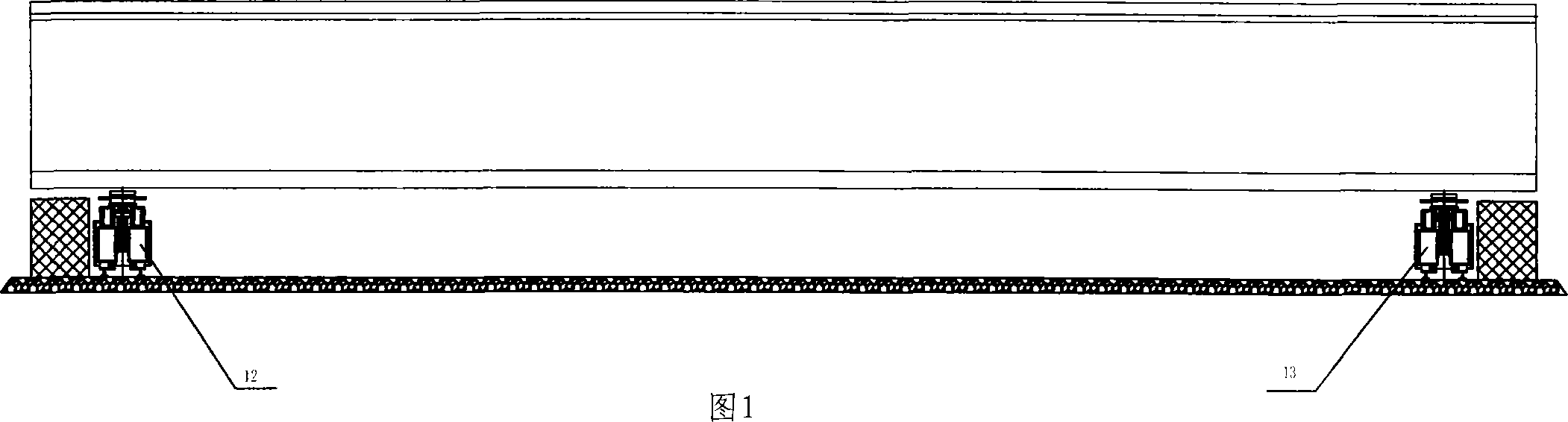
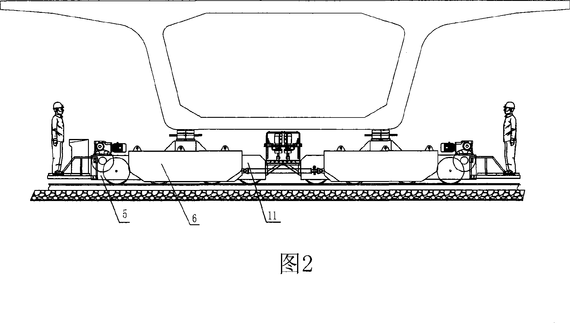
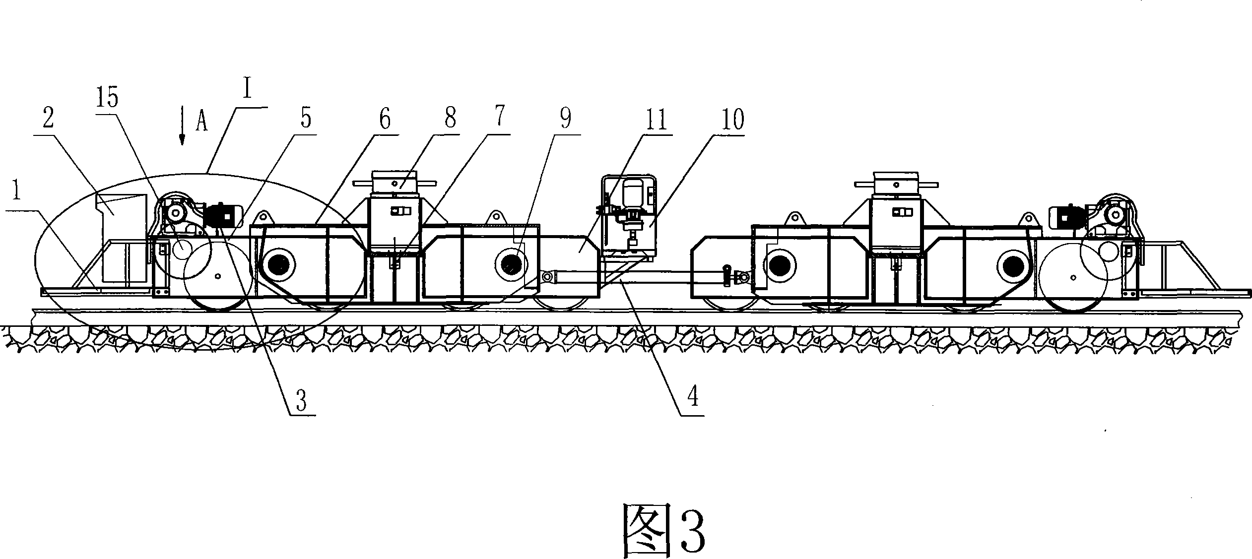
[0020] The present invention is described as follows with reference to accompanying drawing in conjunction with specific embodiment:

[0021] Referring to Fig. 1, 2, 3, 4, the main traversing trolley 12 and the auxiliary traversing trolley 13, the main traversing trolley 12 and the auxiliary traversing trolley 13 are respectively composed of two traveling flat cars, and the two walking parallel The car is rigidly hinged through the balance connecting rod 4, and each flat car includes two active trolleys 5 and two passive trolleys 11, the active trolley and the passive trolley are connected by a balance beam 6, and the jacking cylinder 8 is installed on the side of the flat trolley. On the balance beam 6, a reducer 3 is provided at one end of the balance beam 6, a hydraulic pump station 10 is provided at the other end, and a balance main shaft 9 is provided below, and a pressure pump electrically connected to the PLC control system is installed on the jacking cylinder 8. And th...


PUM


Abstract

A rail mounted beam shifting trolley is composed of a main transverse shifting trolley and an ancillary transverse shifting trolley. The main transverse shifting trolley and the ancillary transverse shifting trolley are composed of two line-fed flat cars respectively, and the present invention is characterized in that a jacking-up oil cylinder and a corresponding hydraulic pump station are arranged on each line-fed flat car. A rotating coder is arranged on the driving trolley of the main transverse shifting trolley and the ancillary transverse shifting trolley, an operating platform is arranged on the driving trolley of the main transverse shifting trolley, and a PLC control system table is arranged in the operating platform. The present invention has the advantages of simple and reasonable structure, high automation, easy operation, safety and reliability, compact structure, easy installation and adjustment, low labor force and efficient beam shifting; and is applied to the industrial large-scale production, and can be taken as a substitution of the current beam shifting trolley.

Description

technical field [0001] The invention relates to mechanical engineering construction equipment, in particular to a rail-type beam-moving trolley used in the field shifting of high-speed railway prefabricated box girders. Background technique [0002] At present, domestic railways, highways and urban bridges are dominated by reinforced concrete structures, and bridge deck components are basically made by prefabrication. For the transitional movement of traditional concrete prefabricated box girders, the beam-moving equipment used is mainly gantry, beam lifting machine, and ordinary beam-moving flat car. Its shortcomings are large volume, high cost, inconvenient operation, especially poor synchronization and safety, low production efficiency, and high labor intensity. At this time, the trolley will tilt, and the running wheels will break away from the track surface, making the prefabricated beam and the ground form a certain angle, causing tilting or even overturning, which ma...

Claims


Application Information

Patent Timeline
IPC IPC(8): E01D21/00
Inventor 王祥军张维友胡仕成龚俊王维兵
Owner 湖南五新智能科技股份有限公司
Why Eureka
Try Eureka