Switch for direct and alternating current operation

A technology of AC operation and contactors, applied in relays, electromagnetic relays, high-voltage/high-current switches, etc., can solve problems such as circuit breaker damage

Active Publication Date: 2008-02-06
SCHALTBAU GMBH
View PDF1 Cites 17 Cited by
  • Summary
  • Abstract
  • Description
  • Claims
  • Application Information

AI Technical Summary

Problems solved by technology

[0008] The moving contact piece must be connected to the input lead through a flexible wire, and the moving contact piece has a large opening stroke, which is the damage factor of the circuit breaker

Method used


Image

  • Switch for direct and alternating current operation
  • Switch for direct and alternating current operation
  • Switch for direct and alternating current operation

Examples


Embodiment Construction

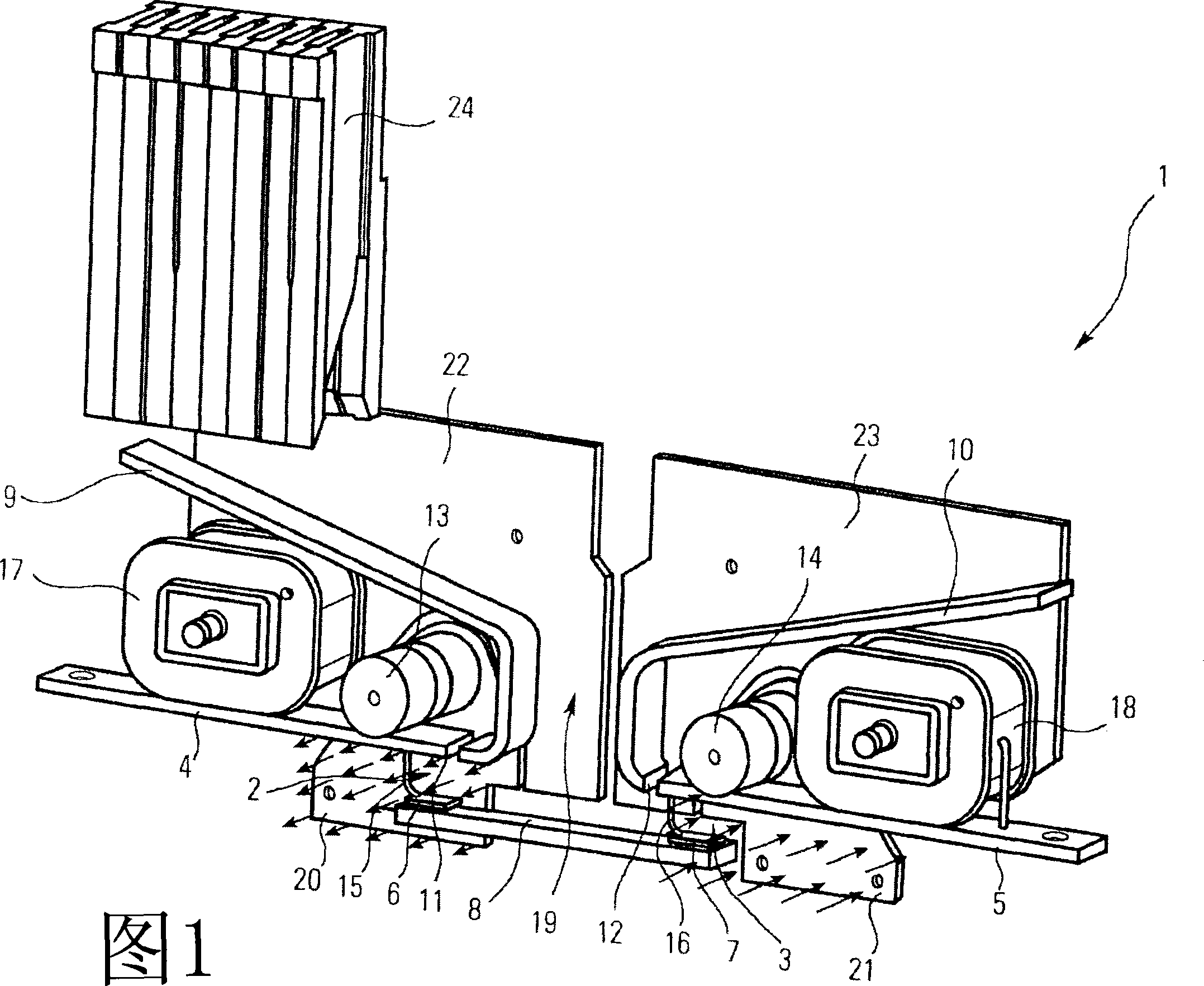
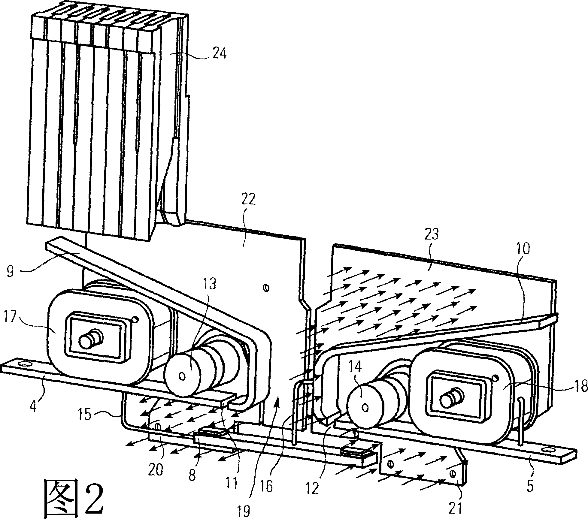
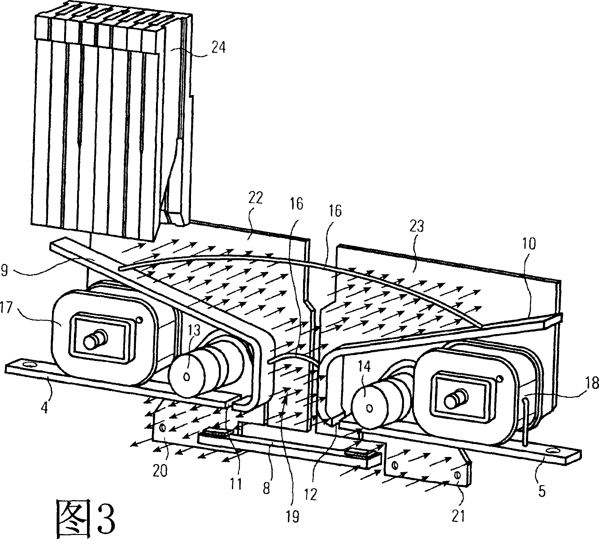
[0021] FIG. 1 shows a perspective view of the inside of the contactor 1 . The contactor comprises two contact points 2,3 each having a fixed contact piece 4,5 and each contact point having a moving contact point 6,7. The moving contact pieces 6 , 7 are arranged on a contact bridge 8 . The contact bridge 8 is movable by a magnetic drive (not shown) and can be shifted from a closed position, in which the moving contact pieces 6, 7 contact the fixed contact pieces 4, 5, to an open position, in which the moving contact pieces 6, 7 Separate from the fixed contacts 4,5. An arc runner 9, 10 is arranged adjacent to the fixed contact piece 4, 5 at each contact point 2, 3 position. Each arc runner 9 , 10 is insulated from the stationary contact piece 4 , 5 by an air gap 11 , 12 , and in addition at least one permanent magnet 13 , 14 is arranged at each contact point 2 , 3 . The permanent magnets 13, 14 are arranged in such a way that their magnetic fields are perpendicular to the arc...


PUM


Abstract

The invention relates to a contactor for direct current and alternating current operation with at least one contact point with a fixed contact and a movable contact, at least one permanent magnet, arranged adjacent to the contact point, for the generation of a permanent magnetic blowout field and at least one coil, arranged adjacent to the contact point, for the generation of an electromagnetic blowout field, for blowing an arc that is formed when opening the contact point into at least one arc chamber. A contactor is to be provided that allows a quick and reliable separation of the contacts and consequently also a quick and reliable extinguishing of the arcs and that allows a structure with a simple design and simple manufacture. For this purpose, the contactor has at least two contact points, wherein the movable contacts are arranged on a contact bridge, at least one permanent magnet is arranged adjacent to each contact point and the permanent magnets assigned to the two contact points are polarised in opposite directions.

Description

technical field [0001] The invention relates to a contactor for DC and AC operation, having at least one contact point, at least one permanent magnet and at least one coil. The contact point has a fixed contact piece and a moving contact piece. The permanent magnet is placed next to the contact point and is used to generate a permanent blow-off magnetic field. The coil is arranged adjacent to the contact point for generating a blow-out electromagnetic field to blow the arc formed when the contact point is opened to at least one arc cavity. Background technique [0002] Such contactors are used, for example, on railway systems for switching loads and for interrupting high-current or high-voltage circuits. During the switching operation, ie when the contacts are opened, an arc is formed between the fixed contact piece and the moving contact piece. The current flow between the contact pieces is maintained due to the arc formed. In addition, the formed arc releases a large a...

Claims


Application Information

Patent Timeline
Patent Type & Authority Applications(China)
IPC IPC(8): H01H50/00H01H9/44
CPCH01H9/44H01H9/443H01H9/34H01H33/14H01H33/12
Inventor 罗伯特·克里利克
Owner SCHALTBAU GMBH
Why Eureka
Try Eureka