Step rear face rotor forming milling cutter and processing technology thereof

A technology for forming milling cutters and processing technology, which is applied in the direction of milling cutters, metal processing equipment, manufacturing tools, etc. It can solve the problems of delay in production cycle, breakage of the small end of milling cutters, and less grinding times, so as to improve production efficiency and reduce The effect of processing costs

Inactive Publication Date: 2008-02-20
DONGFANG TURBINE CO LTD
View PDF0 Cites 11 Cited by
  • Summary
  • Abstract
  • Description
  • Claims
  • Application Information

AI Technical Summary

Problems solved by technology

[0003] Milling cutters that process this type of line generally grind the entire flank during manufacture, and depending on the size of the cutter, the flank width ranges from 3mm to more than 50mm, resulting in a long manufacturing time for the entire cutter and seriously delaying production cycle
At the same time, due to the large grinding area of ​​the flank face, the entire grinding time is long, and the profile grinding wheel wears a lot, so it is not easy to ensure the accuracy of the rotor milling cutter
If the rough machining is carried out by increasing the amount of shovel back, although the length of the grinding surface during fine grinding can be reduced, the ideal length of the flank face cannot be achieved, and after increasing the shovel back, due to the characteristics of the Archimedes spiral , there is more grinding at the smallest diameter of the milling cutter, resulting in poor strength at the smallest tooth, which may easily cause the small end of the milling cutter to break and cause accidents
[0004] However, the width of the groove profile of the rotor has stricter tolerance requirements, so that all such milling cutters have no value for grinding or the number of grinding times is small, and all the processed flanks have not fully exerted their effectiveness, which is a kind of waste

Method used


Image

  • Step rear face rotor forming milling cutter and processing technology thereof
  • Step rear face rotor forming milling cutter and processing technology thereof

Examples


Embodiment Construction

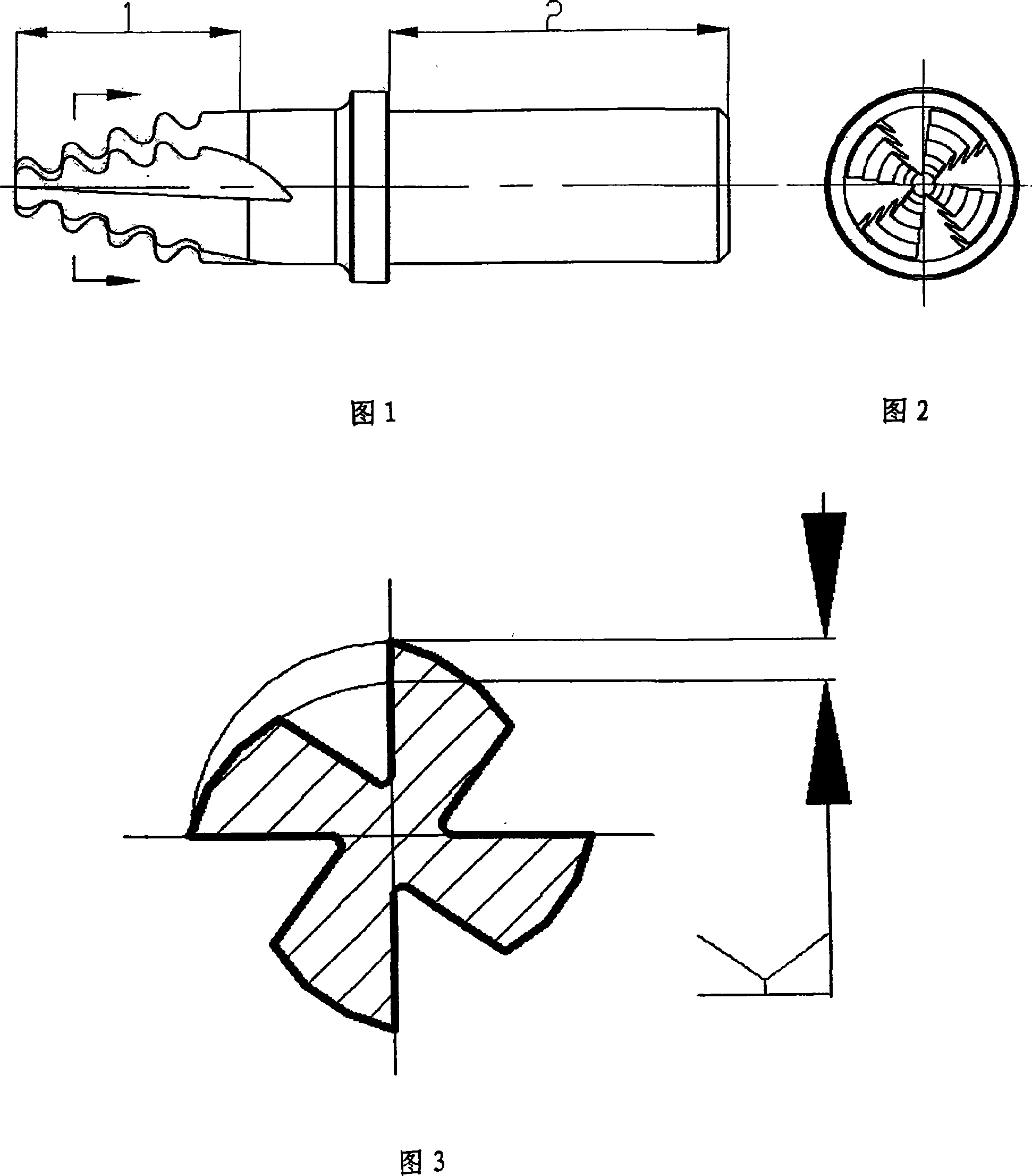
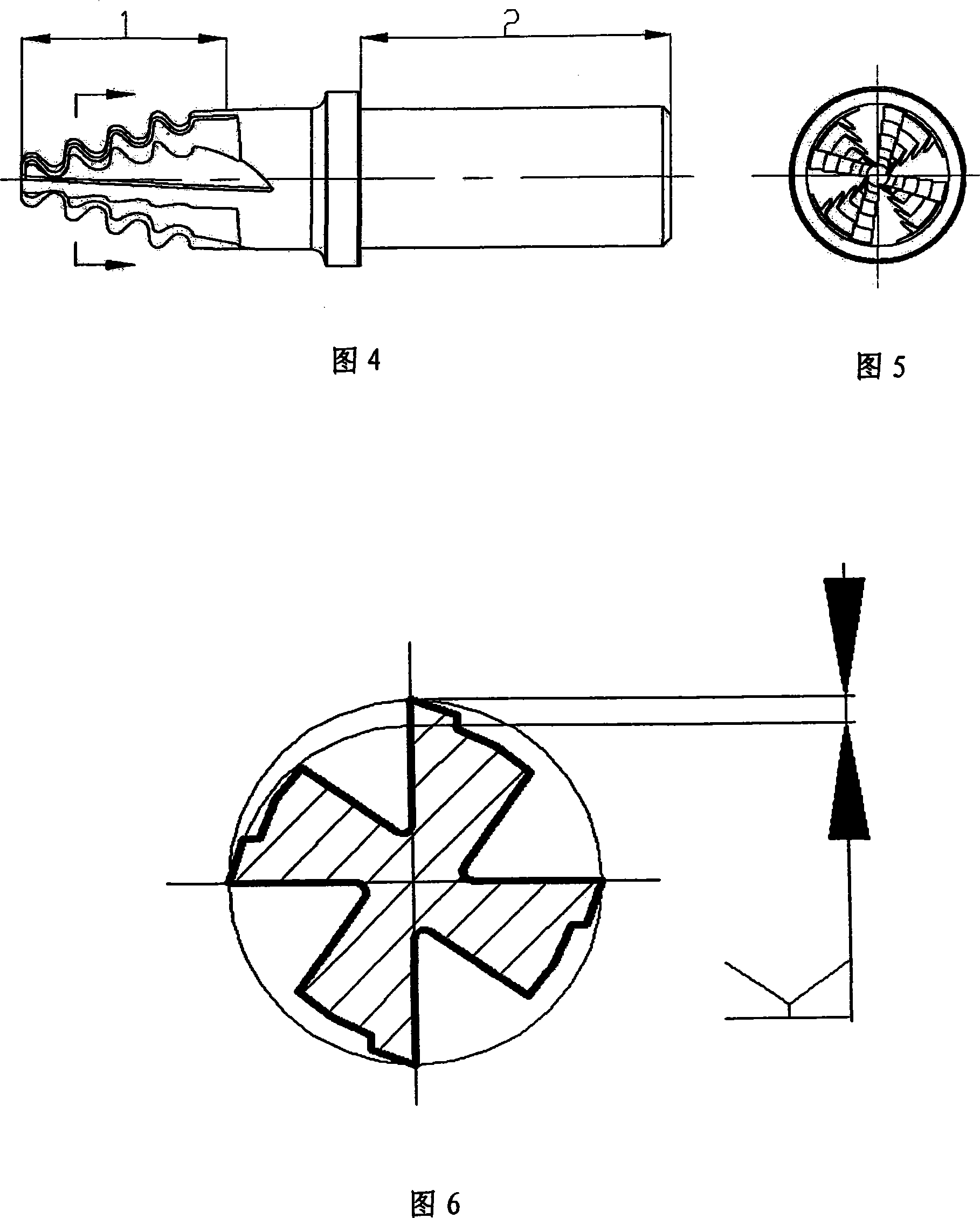
[0016] Referring to Figures 1-6, through the analysis of the groove profile of the rotor, determine the grinding times of the milling cutter under normal use conditions, and on this basis slightly increase the width of the flank to ensure that the cutting edge of the cutter has sufficient Strength, the remaining unnecessary flanks are pre-treated, pre-processing method: the flanks to be pre-treated sink 0.7-1mm lower than the original cutting edge (see Figure 6), and then process the imitation shovel back on this basis . In this way, it can be ensured that this position will not be machined when the flank is ground. Since the grinding area of ​​the flank face is reduced, the tool grinding efficiency is greatly improved. At the same time, due to the less grinding amount of the tool flank, the precision of the grinding wheel profile is maintained for a longer period of time, and the service time of the same grinding wheel is increased, which further improves the efficiency and ...


PUM


Abstract

The present invention discloses a milling cutter molded by the rotor on the step back cutter face and machining technology therein. By analyzing the molded line of the rotor wheel slot, the milling time of the milling cutter in normal conditions is determined. In the foundation, the width of the back cutter face is slightly increased to ensure that the cutter blade has enough intensity; the remaining needless back cutter face undergoes pretreatment to ensure not machining the place in the subsequent milling machining of the back cutter face. As the milling area of the back cutter face is reduced, the milling efficiency of the cutter is greatly improved; meanwhile, as the milling quantity of the cutter is small, the precision of the molded line of the grinding wheel can maintain longer and the service life of a same grinding wheel can be prolonged, which further improves the milling efficiency and the cutter precision; moreover, the invention reduces the machining cost of the rotor wheel slot milling cutter and promises the performance of the cutter not be affected. Moreover, the present invention structure is not only applicable to the relieving cutter, but also effective to the sharp-tooth cutter.

Description

technical field [0001] The invention relates to a special cutting tool for turbomachinery, in particular to a step flank rotor forming milling cutter and its processing technology, which is suitable for processing the profile line of rotor wheel grooves. Background technique [0002] At present, whether it is domestic or foreign rotor groove profile processing, the main use is the high-speed steel milling cutter with integral or butt-welded structure. The main reason is that the cost of the turbomachinery rotor is high, the profile of the wheel groove is complicated, and the precision and roughness of the profile surface are high. Its molded surface does not allow any quality problems. At the same time, because the solid carbide milling cutter is not easy to achieve the diameter required by the profile cutter, or even if it achieves the required diameter, its price is extremely expensive, and the edge of the carbide cutter cannot be very sharp. It is very unfavorable for t...

Claims


Application Information

Patent Timeline
Patent Type & Authority Applications(China)
IPC IPC(8): B23C5/10B23C5/12B23P15/34B23C3/18
Inventor 吴波刘文泽钟成明王强周乐安
Owner DONGFANG TURBINE CO LTD
Why Eureka
Try Eureka