
Yarn cutting and retaining device, and flat knitting machine

A technology for cutting device and knitting yarn, which is applied to flat knitting machines, knitting, and weft knitting with individual moving needles, which can solve the problem of increased installation space and achieve the effect of keeping the cutting device compact and reducing the installation space

Active Publication Date: 2011-03-02
SHIMA SEIKI MFG LTD
View PDF1 Cites 0 Cited by
  • Summary
  • Abstract
  • Description
  • Claims
  • Application Information

AI Technical Summary

Problems solved by technology

The knitting yarn gripping and cutting device disclosed in Patent Document 1 requires three motors and the like as a driving source, so the installation space and the like increase.

Method used


Image

  • Yarn cutting and retaining device, and flat knitting machine
  • Yarn cutting and retaining device, and flat knitting machine
  • Yarn cutting and retaining device, and flat knitting machine

Examples


Embodiment Construction

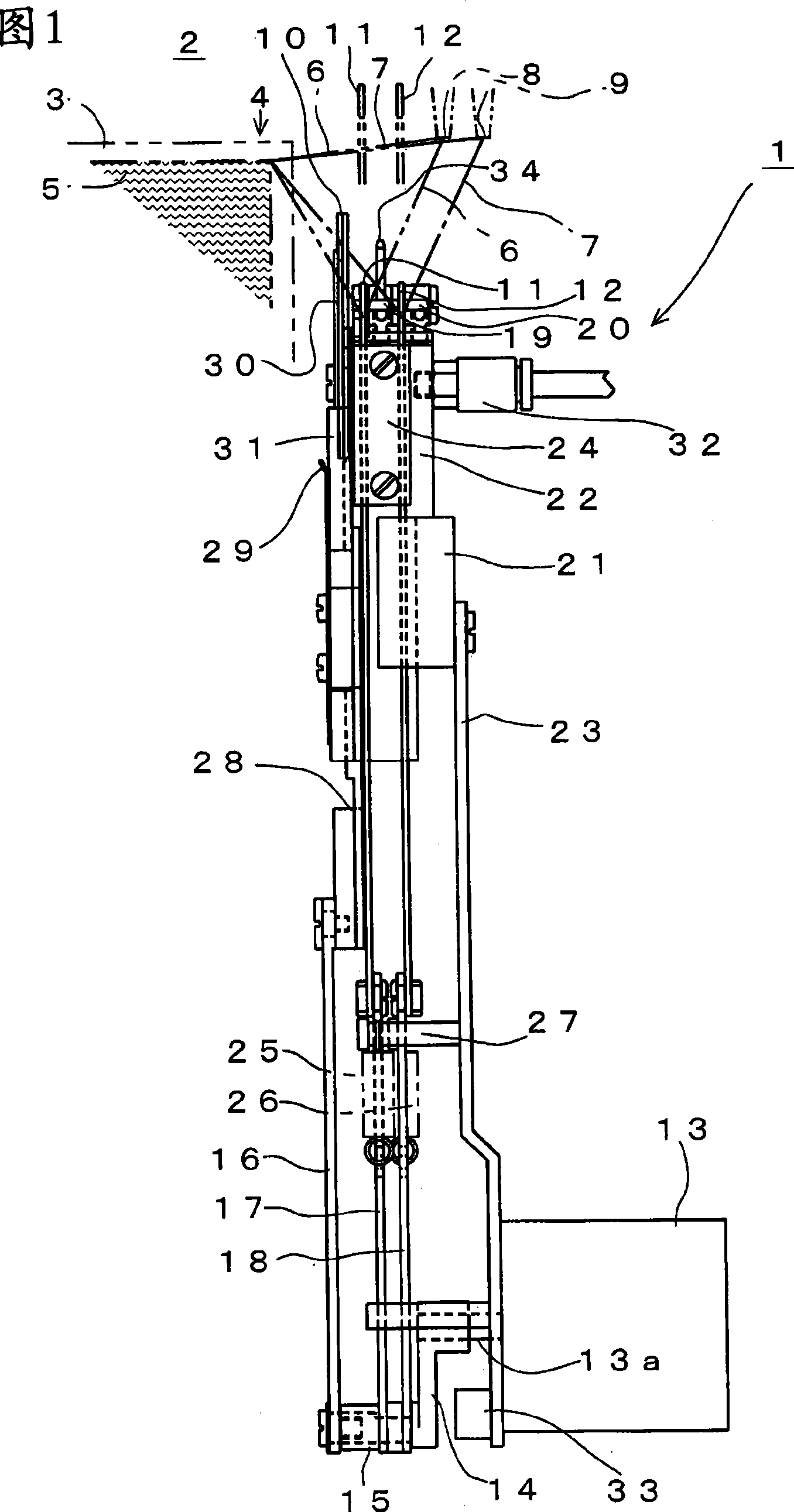
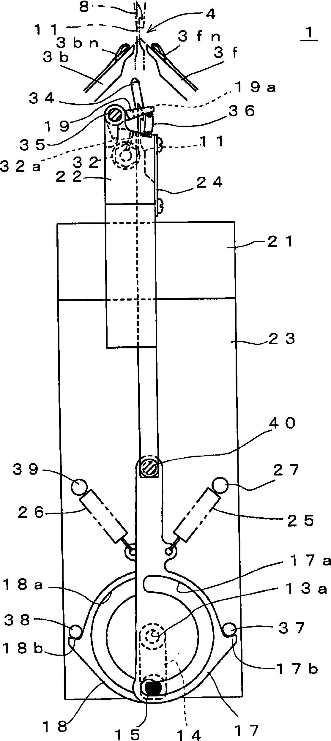
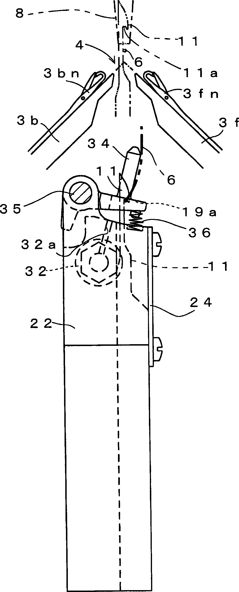
[0063] Figure 1 to Figure 12 A schematic configuration of a knitting yarn holding and cutting device 1 according to an embodiment of the present invention is shown. In addition, in the following description, the part corresponding to the part demonstrated above is attached|subjected with the same reference symbol, and a redundant description is abbreviate|omitted.

[0064] figure 1 A partial configuration of the flatbed knitting machine 2 provided with the knitting yarn holding and cutting device 1 of the present embodiment is briefly shown. The knitting yarn holding and cutting device 1 is provided below the needle bed 4 where the front and rear needle beds 3 face each other or below the side ends of the needle bed 4 in the flatbed knitting machine 2 having the front and rear needle beds 3 . In the flatbed knitting machine 2 , the knitted fabric 5 can be knitted individually by each needle bed 3 , or can be knit in a cylindrical shape while knitting both ends of the knitti...


PUM


Abstract

The invention provides a knitting-yarn maintenance cutting device and a flat knitting machine. A drive pin parts (15) is mounted about the front end of a driving lever (14) mounted on a output axis (13a) as motor (13) of driving source. The drive pin parts (15) is commonly inserted into slot (16a) and arc slots (17a),(18a) of a bonding parts (16) for cutting piece and two bonding parts (17),(18) for bend needles. The bonding parts (16) for cutting piece conveys driving power for making the cutting piece (10) act through output of motor (13). The bonding parts (17),(18) for bend needles transfer and converse the driving power for making the bend needles (11),(12) selectively act through output of motor (13). When each of the bend needles (11),(12) descends, the upper hooked part respectively clamps knitting yarn (6),(7) between the yarn hodling levers (19),(20) to maintain.

Description

technical field [0001] The present invention relates to a knitting yarn holding and cutting device for holding and cutting a knitting yarn supplied from a yarn supply port for knitting a knitted fabric, and a flat knitting machine provided with such a knitting yarn holding and cutting device. Background technique [0002] Conventionally, a yarn gripping device has been used for cutting and separating each product while continuously knitting products with a flatbed loom (for example, refer to Patent Document 1). In the yarn gripping device disclosed in Patent Document 1, a pair of jaws are raised to the path of the knitting yarn from the knitting end of the knitted fabric to the yarn supply port in an open state from the bottom of the tooth gap or the bottom of the tooth gap side end, Close the claws to grasp, and lower the claws holding the knitting yarn to hold the knitting yarn. The lifting action of such jaws is performed by converting the rotational output of the motor ...

Claims


Application Information

Patent Timeline
Patent Type & Authority Patents(China)
IPC IPC(8): D04B15/00D04B15/38D04B35/34D04B7/00
CPCD04B1/22D04B7/30D04B15/40D04B15/48D04B15/56D04B15/60D04B15/96D04B35/02
Inventor 下村博则
Owner SHIMA SEIKI MFG LTD
Learn More