
Thin type display capable of regulating rotation angle range

A display and thin technology, applied in the direction of instruments, identification devices, nonlinear optics, etc., can solve the problems of increasing the cost of the second hinge 174, damage to the second hinge 174, damage to the thin display, etc.

Inactive Publication Date: 2008-02-20
BENQ CORP
View PDF0 Cites 0 Cited by
  • Summary
  • Abstract
  • Description
  • Claims
  • Application Information

AI Technical Summary

Problems solved by technology

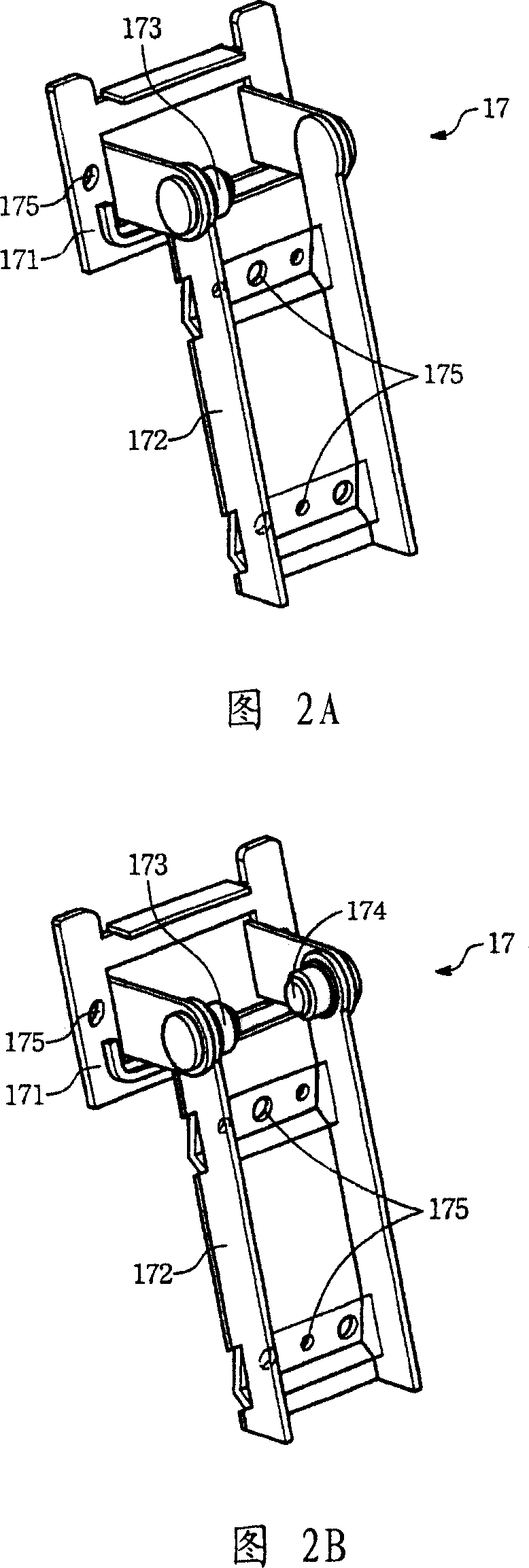
[0011] However, although the pivotal joint device 17 shown in FIG. 2B has improved the problem that the pivotal joint device 17 shown in FIG. Cost required for hinge 174 (FIG. 2B)
In addition, compared with the first hinge 173, because the second hinge 174 needs to exert a relatively large torsion force, it may cause damage to the second hinge 174 due to improper application of pressure, and even damage the thinner hinge 174. Other Structures of Display 10

Method used


Image

  • Thin type display capable of regulating rotation angle range
  • Thin type display capable of regulating rotation angle range
  • Thin type display capable of regulating rotation angle range

Examples


Embodiment Construction

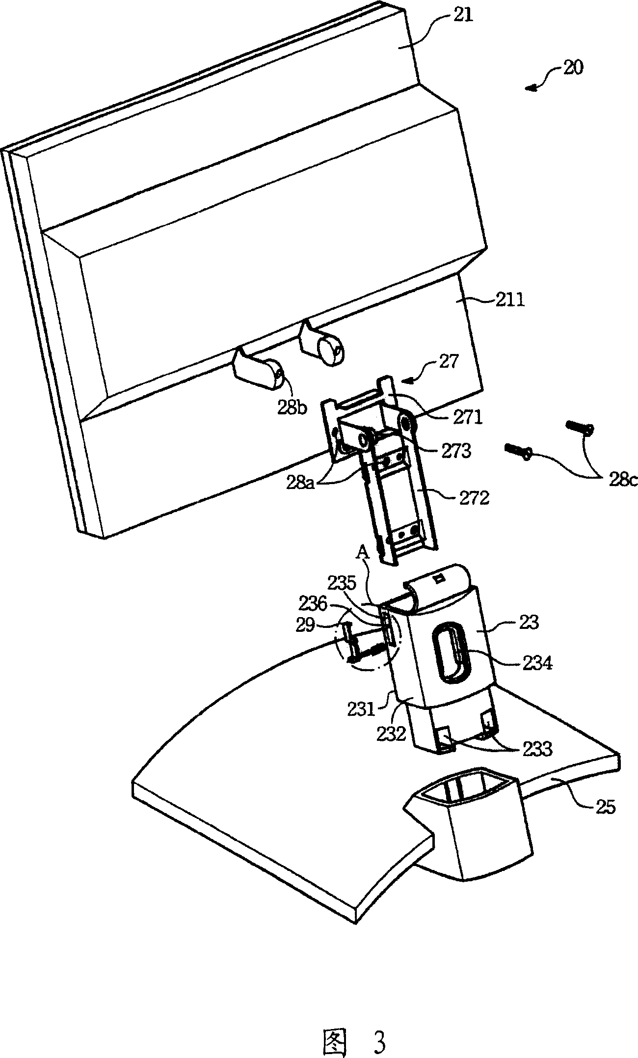
[0055] Please refer to FIGS. 3 and 3A. FIG. 3 is an exploded view of the thin display of the present invention, and FIG. 3A is a partial enlarged view of the area indicated by circle A in FIG. 3. As shown in the figure, a thin display 20 includes a display panel 21, a support arm 23, a base 25, a pivoting device 27, and a resisting unit 29.

[0056] The support arm 23 is used to support the display panel 21, and the base 25 is used to support the support arm 23. With the support arm 23, the display panel 21 can be made to stand above the base 25. The pivoting device 27 is used to pivotally connect the display panel 21 and the support arm 23. Through the pivoting device 27, the display panel 21 can rotate relative to the support arm 23.

[0057] Among them, various embodiments of the thin display 20 may be a liquid crystal display (LCD), a plasma display panel (PDP), and an organic light-emitting diode display (OLED display). ), or a surface conduction electron emitter display (SED...


PUM


Abstract

The utility model discloses a thin type display, comprising a display panel, a bracing arm, a pivot device, a fixing block and a base. The display panel is arranged at the upper end of the bracing arm and the base is arranged at the lower end of the bracing arm. The display panel can be arranged vertically at the upper part of the base through the bracing arm. The pivot device is arranged between the bracing arm and the display panel and a pivot rotation gap is formed between the pivot device and the bracing arm and the rotation gap is used for pivoting the bracing arm and the display panel, making the display panel can rotate relatively to the bracing arm; wherein the bracing arm comprises a first lateral face; the display panel can form a binding status at least together with partial first lateral face. When the binding status is transferred to a separation status for the display panel together the first lateral face due to rotation, a fixing block is fixed into the pivot rotation gap, keeping the separation status for the display panel and the first lateral face.

Description

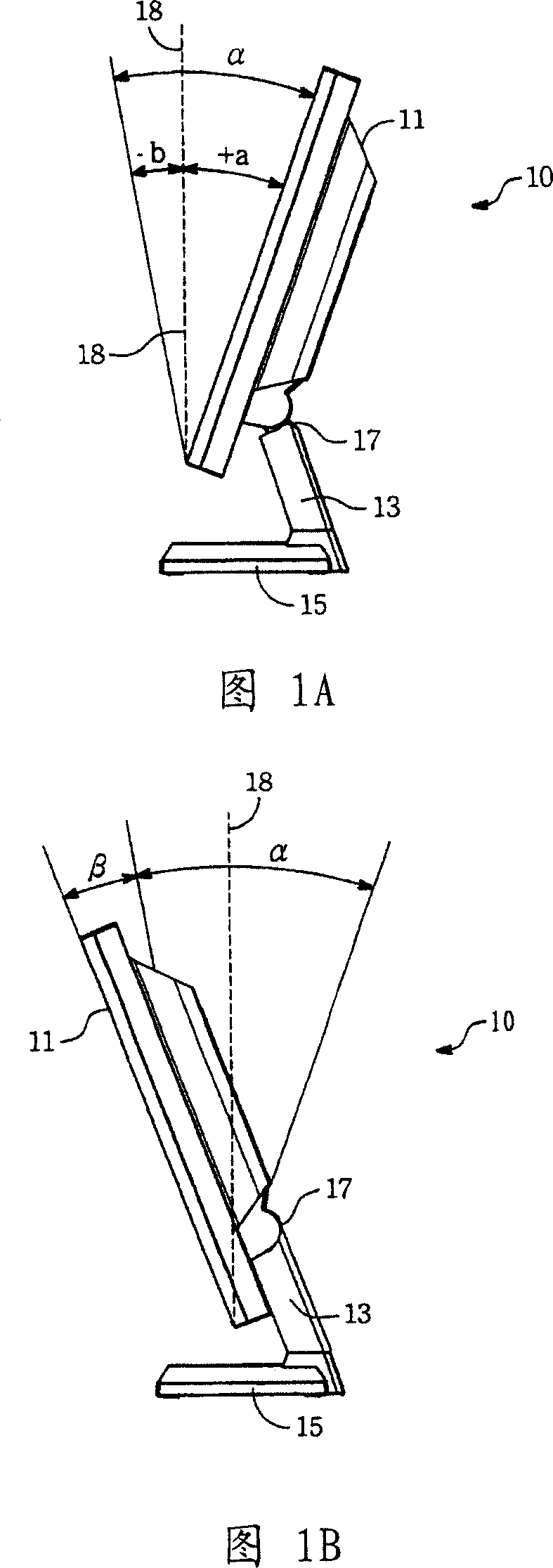
Technical field [0001] The present invention relates to a thin display, in particular to a thin display that can be used to change the pitch angle of a display panel. Background technique [0002] Please refer to FIG. 1A. FIG. 1A is a side view of a conventional thin display 10. The thin display 10 is usually a liquid crystal display. The thin display 10 includes a display panel 11, a supporting arm 13 and a base 15. The display panel 11 is arranged at the upper end of the support arm 13, and the base 15 is arranged at the lower end of the support arm 13. The support arm 13 allows the display panel 11 to stand above the base 15. The thin display 10 further includes a pivoting device 17, and the pivoting device 17 is disposed between the supporting arms 13 of the display panel 11. Through the pivoting device 17, the user can adjust the pitch angle of the display panel 11 according to their own needs. [0003] Generally speaking, when the display panel 11 is used, the display panel...

Claims


Application Information

Patent Timeline
Patent Type & Authority Applications(China)
IPC IPC(8): G02F1/1333G09F9/00
Inventor 林世安
Owner BENQ CORP
Learn More