
Ips-mode LCD device having an improved image quality

A technology of liquid crystal display panel and liquid crystal layer, which can be used in instruments, nonlinear optics, optics, etc., and can solve problems such as misdiagnosis and reduction of image quality.

Inactive Publication Date: 2008-02-20
NEC LCD TECH CORP
View PDF5 Cites 3 Cited by
  • Summary
  • Abstract
  • Description
  • Claims
  • Application Information

AI Technical Summary

Problems solved by technology

For example, in the field of medical equipment, where pictures from X-ray machines are displayed on LCD panels to allow diagnosis of patients, misdiagnosis can occur if afterimages appear after displaying a particular picture for a long time
Also, when using a monitor for broadcasting or television, etc., this afterimage degrades the image quality

Method used


Image

  • Ips-mode LCD device having an improved image quality
  • Ips-mode LCD device having an improved image quality
  • Ips-mode LCD device having an improved image quality

Examples


Embodiment Construction

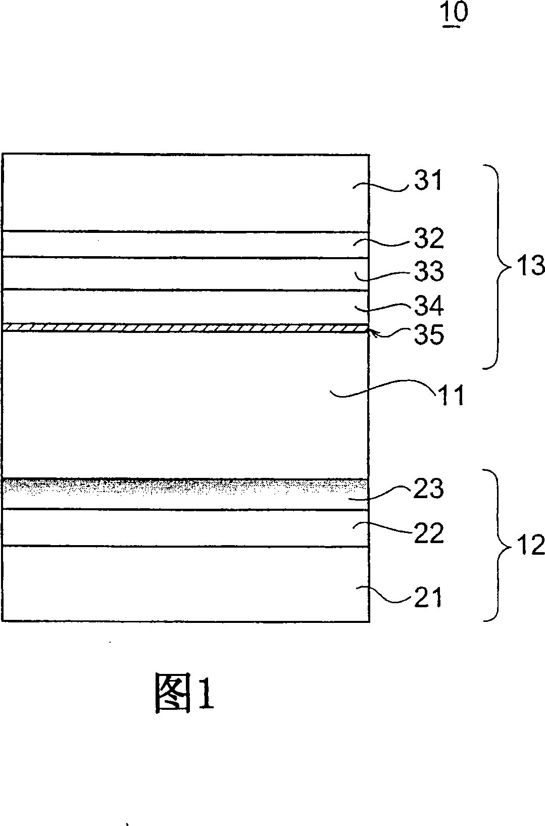
[0024] Exemplary embodiments of the present invention will now be described with reference to the drawings, in which like constituent elements are denoted by like reference numerals throughout. FIG. 1 shows a cross-sectional view of an LCD panel according to a first embodiment of the present invention. The LCD panel, generally indicated by numeral 10, is LEF-mode and comprises an LC layer 11 comprising LC molecules therein, an active matrix substrate 12 mounted thereon, and a counter substrate 13 A drive electrode or electrode film for applying a lateral electric field to the LC layer 11, the counter substrate 13 is opposed to the active matrix substrate 12 with the LC layer 11 interposed therebetween.

[0025] The active matrix substrate 12 includes a glass substrate 21 on which a functional layer structure 22 and a first alignment film 23 are continuously formed. The functional layer structure 22 includes a semiconductor layer, a plurality of conductive layers, and a plural...


PUM


Abstract

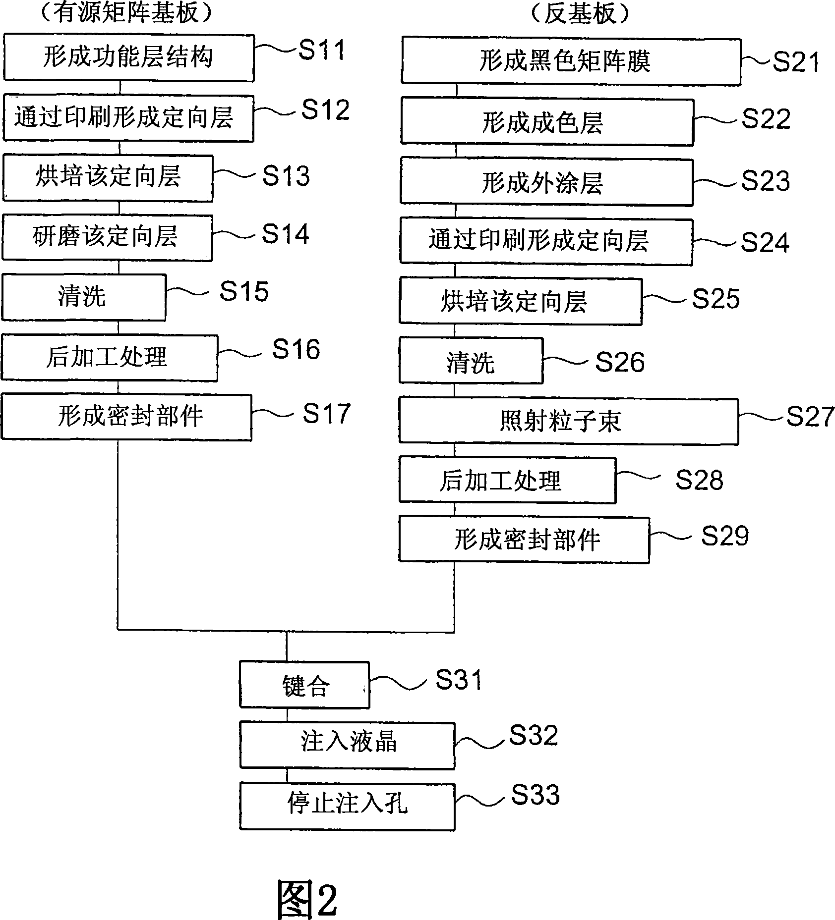
A LCD panel includes a LC layer, an active-matrix substrate including an electrode layer for applying a lateral electric field to the LC layer, and a counter substrate opposing the active-matrix substrate with an intervention of the LC layer 11. The active-matrix substrate includes a first alignment film formed in the surface which touches the LC layer 11 by the rubbing technique is formed, and second alignment film 35 formed in the surface which touches the LC layer 11 by the particle beam glaring technique is formed on the counter substrate 13.

Description

[0001] This application is based upon and claims the benefit of priority from Japanese Patent Application No. 2006-223195, the disclosure of which is hereby incorporated by reference in its entirety. technical field [0002] The present invention relates to a liquid crystal display device (LCD), and more particularly, to a transverse electric field LCD device, such as an in-plane switching mode (IPS-mode) LCD device. Background technique [0003] An LCD device includes a backlight unit and an LCD panel arranged on a front or light emitting side of the backlight unit. The LCD panel performs optical switching with respect to pixels arranged in a matrix therein, and displays images on a screen. In addition, LCD panels can also display video images by continuously performing optical switching of each pixel. [0004] In recent years, LCD devices are widely used in vehicle equipment fields such as car navigation systems, various industrial devices, medical or broadcasting devices...

Claims


Application Information

Patent Timeline
Patent Type & Authority Applications(China)
IPC IPC(8): G02F1/1362G02F1/1337G02F1/1333
CPCG02F2001/133765G02F1/13378G02F1/134363G02F1/133765
Inventor 佐佐木洋一铃木照晃杉本光弘沟口亲明田中大充
Owner NEC LCD TECH CORP
Learn More