Heat pipe with compound capillary structure and manufacturing method thereof

A capillary structure and heat pipe technology, applied in the field of heat pipes, can solve the problems of high manufacturing cost, lack of capillary structure, and inability to fully exert heat transfer efficiency, and achieve the effect of fast production rate and low production cost.

Inactive Publication Date: 2008-02-27
MITAC COMP (SHUN DE) LTD +1
View PDF1 Cites 2 Cited by
  • Summary
  • Abstract
  • Description
  • Claims
  • Application Information

AI Technical Summary

Problems solved by technology

[0005] The above-mentioned tubular or flat heat pipes only have a capillary structure. Therefore, in practice, the working fluid in the accommodation space is transformed into a gaseous state or a liquid state. Corresponding to different capillary structures, therefore, the efficiency of heat transfer will not be fully utilized
Although it is a feasible technology to manufacture different capillary structures on the inner wall of the shell by etching, its manufacturing cost is obviously too high, and it is not acceptable to ordinary users

Method used


Image

  • Heat pipe with compound capillary structure and manufacturing method thereof
  • Heat pipe with compound capillary structure and manufacturing method thereof
  • Heat pipe with compound capillary structure and manufacturing method thereof

Examples


Embodiment Construction

[0020] In order to have a further understanding of the purpose, structure, features, and functions of the present invention, the following detailed descriptions are provided in conjunction with the embodiments.

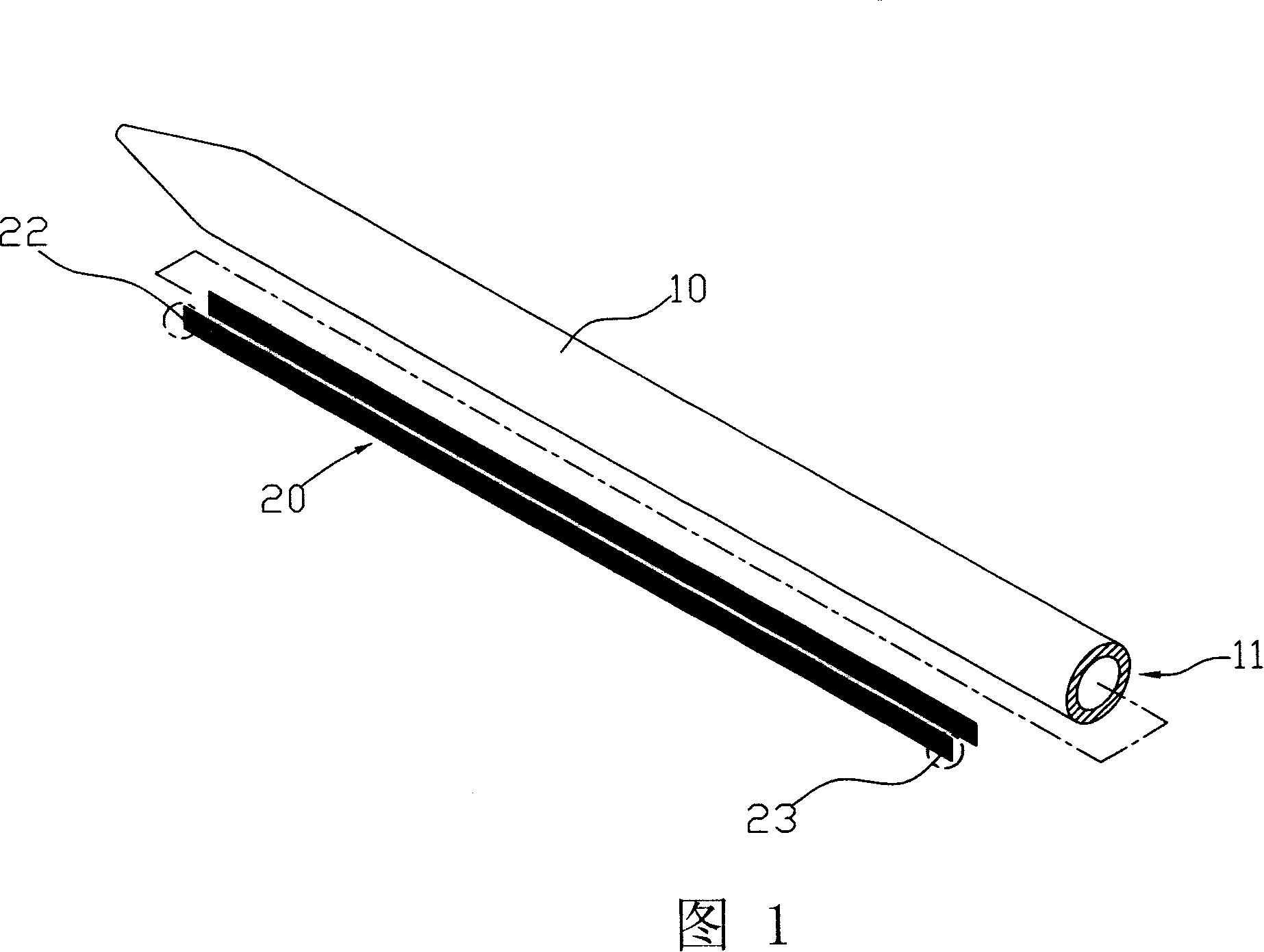
[0021] First please refer to Fig. 1, Fig. 2 and Fig. 3, which is a heat pipe with a composite capillary structure provided by the first embodiment of the present invention, including a hollow shell tube 10, at least one metal sheet 20 and a filling in the middle The working fluid in the hollow tube 10 (not shown in the figure).

[0022] The hollow shell tube 10 is a material with good thermal conductivity, and it is made into a predetermined length and bent shape according to the requirements. It has at least one open end 11, and the open end 11 can be used for the metal sheet 20 and the working fluid to be inserted into the hollow The shell tube 10 is closed after the heat pipe is fabricated.

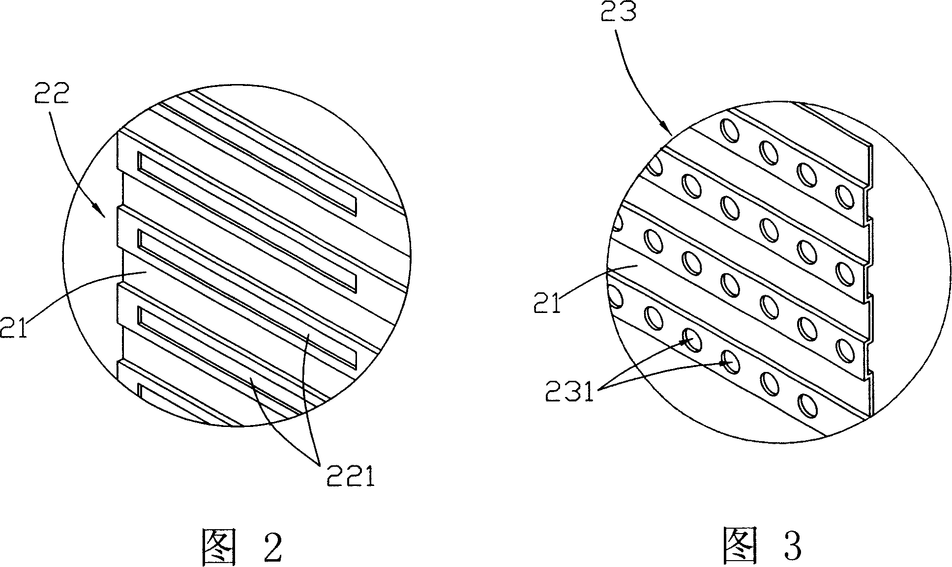
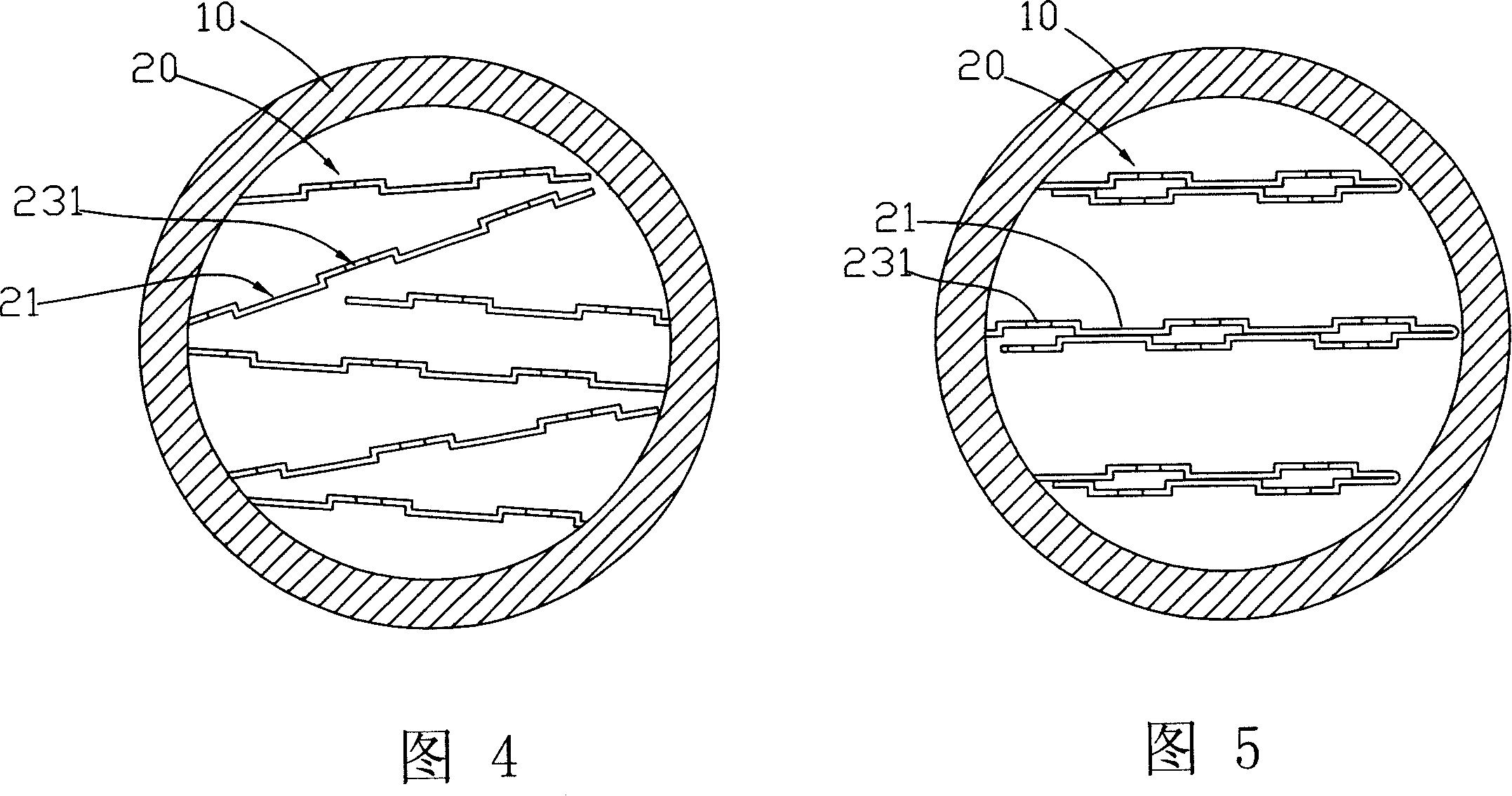
[0023] The shape of the metal sheet 20 is to match the shape of the holl...


PUM


Abstract

This invention discloses a heat tube of combined capillary structure and its producing method. The heat tube is composed of sealed hollow shell tube and at least one metal sheet. Working fluid is filled in the hollow shell tube. The metal sheet passes through the said shell tube and is divided into one first capillary section and one second capillary section. The first capillary section has several first capillary structures, which are used to absorb working fluid. The second capillary section has several second capillary structures, which are used to absorb working fluid. The capillary force generated by the first capillary structure is not the same as that of the second capillary structure. Thus, it makes the liquid working fluid flow in preset direction. This invention is simple and has good heat transferring efficiency.

Description

technical field [0001] The present invention is related to heat pipes, in particular to a heat pipe with several different capillary structures and its manufacturing method. Background technique [0002] At present, the basic structure of the heat pipe generally includes: a shell, which is made of a material with good thermal conductivity, and forms a sealed receiving space. Capillary structures of different shapes. An appropriate amount of working fluid is injected into the containing space, and it can be water, ethanol or acetone and other materials. [0003] Through the characteristics that the working fluid can be accommodated in the sealed accommodation space, undergo a gas-liquid two-phase change, and can move along the range of the capillary structure, the heat pipe has the function of quickly and effectively transferring heat energy. Therefore, the general heat pipe is defined as a heating section (or evaporation section) for heat absorption, a cooling section (or ...

Claims


Application Information

Patent Timeline
Patent Type & Authority Applications(China)
IPC IPC(8): F28D15/04
Inventor 萧惟中
Owner MITAC COMP (SHUN DE) LTD
Why Eureka
Try Eureka