Voltage buffer and its source electrode driver
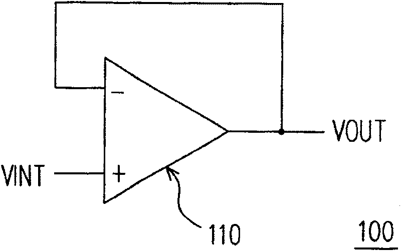
A voltage buffer and current source technology, applied in instruments, static indicators, etc., can solve the problems of LCD display quality degradation, high load capacitance at the panel end, and low voltage buffer 100 slew rate, so as to improve the display image. quality, the effect of improving the slew rate
- Summary
- Abstract
- Description
- Claims
- Application Information
AI Technical Summary
Problems solved by technology
Method used
Image
Examples
Embodiment Construction
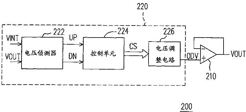
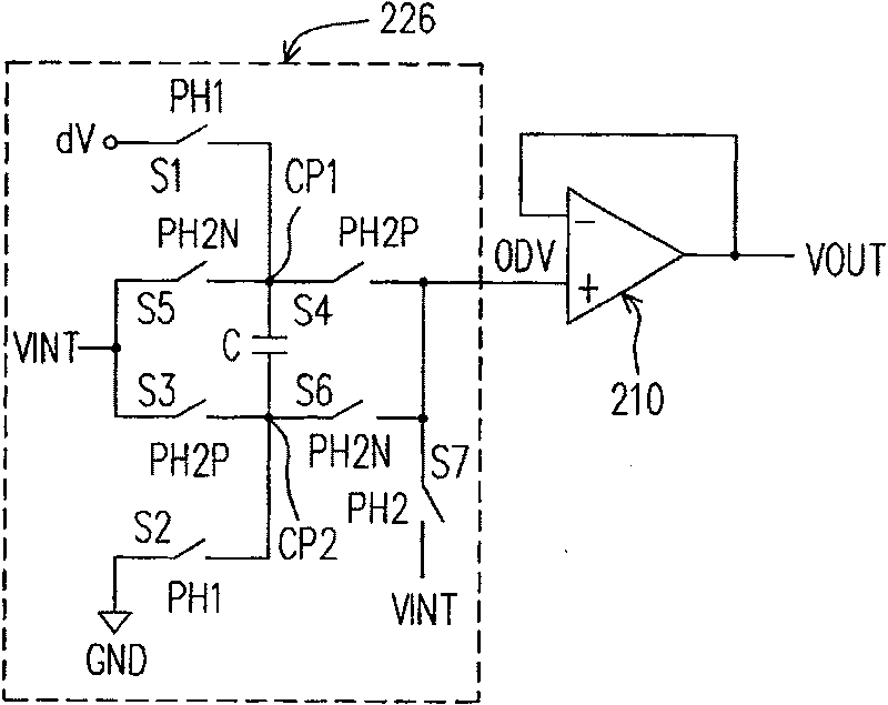
[0092] figure 2 is a circuit block diagram of a voltage buffer according to an embodiment of the present invention. The voltage buffer 200 includes an operational amplifier 210 and an overdrive unit 220 . The operational amplifier 210 has a positive input terminal, a negative input terminal and an output terminal, and the output terminal is coupled to the negative input terminal to form a negative feedback structure. The voltage output by the output terminal is an output voltage VOUT. The overdrive unit 220 is coupled between an input voltage VINT and the operational amplifier 210 for comparing the input voltage VINT and the output voltage VOUT, and outputting an overdrive voltage ODV to the positive input terminal of the operational amplifier 210 .
[0093] Wherein, according to the comparison result of the overdrive unit 220, if the input voltage VINT is greater than the output voltage VOUT, then the overdrive voltage ODV is greater than the input voltage VINT; if the inp...
PUM
 Abstract
Description
Claims
Application Information
 - R&D
- Intellectual Property
- Life Sciences
- Materials
- Tech Scout
- Unparalleled Data Quality
- Higher Quality Content
- 60% Fewer Hallucinations
Browse by: Latest US Patents, China's latest patents, Technical Efficacy Thesaurus, Application Domain, Technology Topic, Popular Technical Reports.
© 2025 PatSnap. All rights reserved.Legal|Privacy policy|Modern Slavery Act Transparency Statement|Sitemap|About US| Contact US: help@patsnap.com


