Display panel drive apparatus

a technology of drive apparatus and display panel, which is applied in the direction of electric variable regulation, process and machine control, instruments, etc., can solve the problems of unfavorable brightness of displayed images, and achieve the effect of enhancing the output drive capacity of the amplifier 323, reducing the variation in the value of current control voltage ictrl, and enhancing the output drive capacity of the amplifier

Active Publication Date: 2009-09-03
LAPIS SEMICON CO LTD
View PDF5 Cites 6 Cited by
  • Summary
  • Abstract
  • Description
  • Claims
  • Application Information

AI Technical Summary

Benefits of technology

[0016]One solution to reduce the variation in the value of the current control voltage ictrl is to enhance the output drive capacity of the amplifier 323 producing the current control voltage ictrl. However, because the current control voltage ictrl signal is usually connected to the gates of many PMOS devices, i.e., it has a large load capacitance, and because the variation is caused by output switching, it is difficult to configure the amplifier 323 that is able to sufficiently suppress the variation.
[0017]An object of the present invention is to provide a display panel drive apparatus which can keep display brightness constant even if the current control voltage ictrl varies, thus preventing the occurrence of unevenness in brightness without imparting an excess drive capacity onto the amplifier 323.
[0019]The clock generating circuit may shorten the pulse period when the current control voltage increases. The clock generating circuit may elongate the pulse period when the current control voltage decreases. Each output driver may include a drive pulse generating circuit to generate a drive pulse, whose pulse width corresponds to brightness data, in synchronization with the clock signal. Each output driver may also include a current source circuit to be switched on and off by the drive pulse, thereby generating a current pulse whose amplitude corresponds to the current control voltage. This current pulse may be used as the brightness pulse. The clock generating circuit may include at least one mirror current source circuit to generate a mirror current having a magnitude based on the current control voltage. The clock generating circuit may also include an integration circuit to integrate the mirror current. The clock generating circuit may include a pulse signal generating unit to generate, as the clock signal, a pulse signal having a pulse period based on integration time until an integral calculated by the integration circuit reaches a threshold value. The mirror current source circuit may include a mirror current controller to control the magnitude of the mirror current depending on the number of generated pulses of the pulse signal. The output drivers may be spatially arranged in parallel with each other such that the output drivers are divided into two groups and the clock generating circuit is sandwiched between the two groups of the output drivers. The output drivers and clock generating circuit may be provided on the same substrate, forming an integrated circuit.

Problems solved by technology

Further, a change in the drain voltage causes the gate voltage of the PMOS device m1—i to change via parasitic capacitance between the gate and drain.
Since the display panel 100 displays an image with brightness corresponding to the drive current Ia_1 varying with the amount of the drive charge Qa_1, there is a problem that unevenness occurs in the brightness of the displayed image if the value of the drive charge amount Qa_1 varies.
However, because the current control voltage ictrl signal is usually connected to the gates of many PMOS devices, i.e., it has a large load capacitance, and because the variation is caused by output switching, it is difficult to configure the amplifier 323 that is able to sufficiently suppress the variation.

Method used


Image

  • Display panel drive apparatus
  • Display panel drive apparatus
  • Display panel drive apparatus

Examples


first embodiment

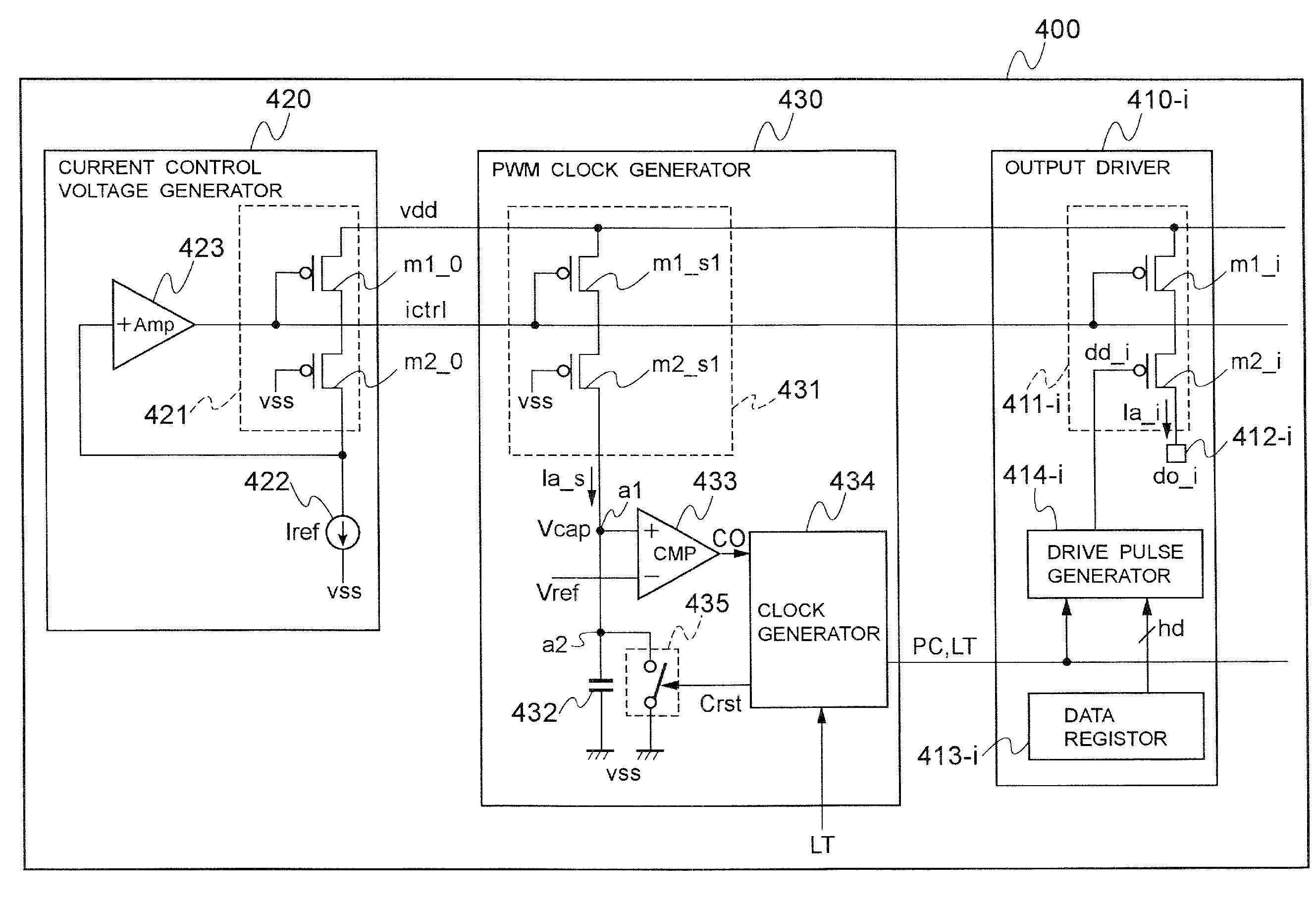
[0035]Referring to FIG. 4, illustrated is a block diagram of a display panel drive apparatus 400 according to the first embodiment of the present invention. The display panel drive apparatus 400 drives a display panel and includes an output driver 410-i, a current controlling voltage generating circuit 420, and a PWM clock generating circuit 430. The display panel drive apparatus 400 usually includes other output drivers in addition to the output driver 410-i, but only the output driver 410-i is shown in the figure for simplicity of description. The total number of output drivers included in the display panel drive apparatus 400 is denoted as n, and the i is a positive integer from 1 to n. Also, a group of cathode drivers included in the display panel drive apparatus 400 are not shown for simplicity of description.

[0036]The configuration and operation of the display panel drive apparatus 400 will be described with reference to FIG. 4 and FIG. 5. FIG. 5 illustrates operation waveform...

second embodiment

[0069]FIG. 8 is a block diagram showing a display panel drive apparatus 400 according to the second embodiment. The configurations of the output driver 410-i and the current controlling voltage generating circuit 420 are the same as in the first embodiment. The differences from the first embodiment will be mainly described below. The PWM clock generating circuit 430 includes mirror current source circuits 431-1 and 431-2. A current control signal cc[1] from the clock producing circuit 434 is introduced to the mirror current source circuit 431-1, and a current control signal cc[2] from the clock producing circuit 434 is introduced to the mirror current source circuit 431-2. A mirror current Ia_s1 is generated from the mirror current source circuit 431-1, and a mirror current Ia_s2 is generated from the mirror current source circuit 431-2.

[0070]The configurations of the PMOS devices m1—s1 and m2—s1 constituting the mirror current source circuit 431-1 are the same as those of the PMOS ...


PUM


Abstract

A display panel drive apparatus which can keep display brightness constant, thus preventing the occurrence of unevenness in brightness. The drive apparatus includes a current controlling voltage generating circuit to generate a current control voltage. The drive apparatus also includes a plurality of output drivers to supply brightness pulses whose amplitude is decided based on the current control voltage respectively onto data lines of a display panel in synchronization with a clock signal. The drive apparatus also includes a clock generating circuit to generate a pulse signal of a pulse period based on the current control voltage as the clock signal.

Description

BACKGROUND OF THE INVENTION[0001]1. Field of the Invention[0002]The present invention relates to a display panel drive apparatus.[0003]2. Description of the Related Art[0004]In recent years, the development of display panels using light-emitting elements such as organic EL elements has advanced, and display apparatuses having such display panel mounted thereon are becoming popular. A drive apparatus and method for organic EL elements on a display panel is disclosed in, for example, Japanese Patent Application Kokai (Laid-Open) No. 2000-100563 (Reference 1). The drive apparatus of Reference 1 includes a switching device serially connected to an organic EL device and a control unit for switching periodically on and off the switching device, thereby periodically supplying a certain amount of drive current to the organic EL device. This drive apparatus reduces brightness drop due to the degradation of the organic EL device.[0005]There are two methods of controlling display gradation emp...

Claims


Application Information

Patent Timeline
Patent Type & Authority Applications(United States)
IPC IPC(8): H05B41/36
CPCG09G3/2014G09G3/3216G09G2320/0233G09G2310/0259G09G2310/066G09G3/3283
Inventor SHIMIZU, NOBUYUKI
Owner LAPIS SEMICON CO LTD
Why Eureka
Try Eureka