

Nonaqueous electrolyte secondary battery
A non-aqueous electrolyte, secondary battery technology, used in non-aqueous electrolyte batteries, secondary batteries, lithium batteries, etc., can solve the problem of easy expansion of short-circuit parts, achieve excellent vibration resistance, prevent winding displacement, high The effect of the energy output characteristic
- Summary
- Abstract
- Description
- Claims
- Application Information
AI Technical Summary
Problems solved by technology
Method used
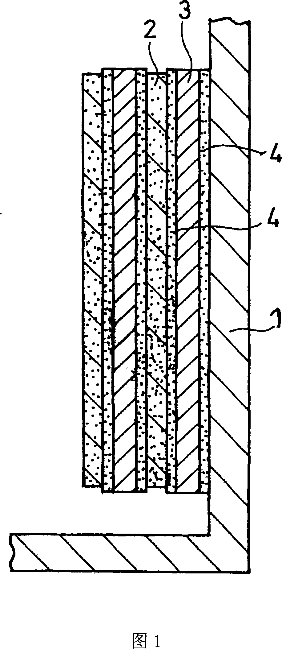
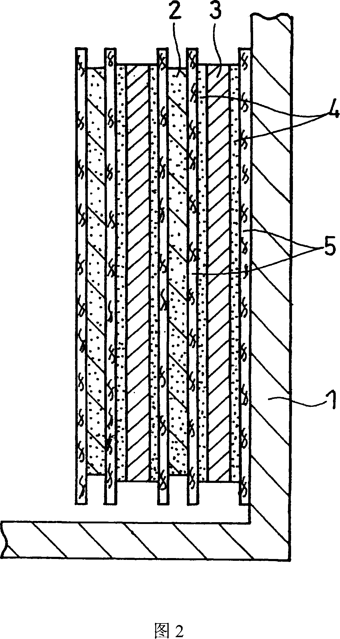
Image

Examples
Embodiment 1
[0092] (Battery 1)
[0093] (production of positive electrode)
[0094] 30 kg of LiNi as the cathode active material was stirred by using a double-arm kneader 0.71 co 0.2 al 0.05 mn 0.02 Mg 0.02 o 2 , 10 kg of polyvinylidene fluoride (PVDF) in N-methyl-2-pyrrolidone (NMP) (#1320, purchased from Kureha Chemical Industry Co., Ltd. (solid content: 12 wt %)) solution, 900 g of acetylene as a conductive agent black, and an appropriate amount of NMP to prepare positive electrode active material mixed slurry. The slurry thus obtained was coated on both surfaces of an aluminum foil (thickness: 15 μm) as a current collector, which was then dried and rolled until its total thickness reached 108 μm, thereby producing a positive electrode plate. Subsequently, the positive electrode plate was cut such that the size of the positive electrode active material on each surface of the current collector was 56 mm in width and 600 mm in length, thereby manufacturing a positive electrode. T...
Embodiment 2
[0141] (Battery 12~35)
[0142] Batteries 12-35 are manufactured in the same manner as battery 2, except that the general formula (1) is used: LiNi 1-a-b-c-d co a al b m 1 c m 2 d o 2 positive active material shown, and M 1 and M 2 Use the elements shown in Table 3, and Ni, Co, Al, M 1 and M 2 The change of the molar ratio is shown in Table 3. Here, M 2 Contains 2 to 4 elements. m 2The molar ratios of each element contained in are the same. The molar ratio d is the element M in the oxide shown in general formula (1) 2 total molar ratio.
[0143] Table 3 (to be continued)
[0144] LiNi 1-a-b-c-d co a al b m 1 c m 2 d o 2
Co's
The molar ratio of
a
Al's
The molar ratio of
b
m 1 of
The molar ratio of
c
m 1 type
m 2 of
The molar ratio of
d
m 2 type
Ni's
The molar ratio of
battery 2
0.2
0.05
...
Embodiment 3
[0162] (Battery 36~64)
[0163] Batteries 36-64 are manufactured in the same manner as battery 2, except that the general formula (2): LiNi a co b mn c m 3 d o 2 Positive electrode active materials shown, along with the molar ratio a of nickel, b of cobalt, c of manganese, and the element M 3 The type and molar ratio d of the changes are shown in Table 5.
[0164] Table 5 (to be continued)
[0165] LiNi a co b mn c m 3 d o 2
Molar ratio of Ni
a
molar ratio of Co
b
Molar ratio of Mn
c
m 3 type
m 3 molar ratio
d
battery 36
0.2
0.4
0.4
-
-
battery 37
0.25
0.375
0.375
-
-
battery 38
0.5
0.25
0.25
-
-
battery 39
0.55
0.225
0.225
-
-
battery 40
0.4
0.2
0.4
-
-
battery 41
0.375
0.25
0.375
...
PUM
| Property | Measurement | Unit |
|---|---|---|
| thickness | aaaaa | aaaaa |
| thickness | aaaaa | aaaaa |
| thickness | aaaaa | aaaaa |
Abstract
Description
Claims
Application Information