Multiple degrees of freedom soft human-imitated finger

A degree of freedom and flexible technology, applied in the field of artificial fingers, can solve the problems of short effective stroke, inflexible movement, unstable movement process, etc., and achieve the effect of long effective stroke, good stability, and not easy to bend and deform

Inactive Publication Date: 2008-03-05
ZHEJIANG UNIV OF TECH
View PDF1 Cites 10 Cited by
  • Summary
  • Abstract
  • Description
  • Claims
  • Application Information

AI Technical Summary

Problems solved by technology

[0004] In order to overcome the deficiencies of the pneumatic flexible artificial finger in the prior art, such as unstable motion process, short effective stroke, and inflexible motion, the present invention provides a multi-freedom finger with long effective motion stroke, stable motion process, flexible motion, and more complex motion. Highly flexible anthropomorphic fingers

Method used


Image

  • Multiple degrees of freedom soft human-imitated finger

Examples


Embodiment 1

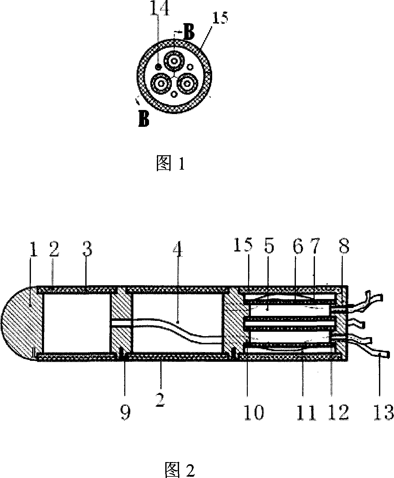
[0016] Referring to the accompanying drawings, this embodiment is a five-degree-of-freedom flexible anthropomorphic finger, including three rigid bodies 1, three thick rubber tubes and an end cap 8, the thick rubber tubes and rigid bodies 1 are arranged alternately in sequence, and the left end of the figure is assumed to be the finger head , the right end of the figure is the bottom of the finger, the two thick rubbers near the head of the finger are the front thick rubber tube 2, the thick rubber tube near the bottom of the finger is the rear thick rubber tube 15, and the end connection end of the rear thick rubber tube 15 Cover 8, the two ends of the thick rubber tube are sealed and connected with the rigid body 1 and the end cover 8 by superglue. A restraint steel wire 9 is also installed in one side of the two front thick rubber tubes 2, and the restraint steel wire 9 is located on the same side of the two front thick rubber tubes 2, and is fixed on the rigid body by screw...

Embodiment 2

[0021] Referring to Fig. 1, the difference between the present embodiment and the first embodiment is that a helical wire 3 is also nested in the walls of the three thick rubber tubes, and the restraining steel wire 9 is connected to the front thick rubber tube 2 in the wall. Each turn of the helical wire 3 is wound. When gas is fed into the first working chamber, the helical wire 3 can limit the radial expansion of the wall of the thick rubber tube and avoid the radial deformation of the fingers. The tube walls of the three thin rubber tubes 6 are also nested with small thin helical wires 7, so that the thin rubber tubes 6 have a certain rigidity and avoid being difficult to control because the thin rubber tubes 6 are too soft.

Embodiment 3

[0023] This embodiment is a four-degree-of-freedom flexible anthropomorphic finger. The difference between this embodiment and Embodiment 1 is that this embodiment includes two rigid bodies and two thick rubber tubes, of which there is only one front thick rubber tube near the finger head ; Therefore, there is only one first working chamber, and there is only one vent pipe connected with the first working chamber; there are 5 holes on the end cover, and there is only one hole connected to the vent pipe of the front thick rubber tube. . Other parts of this embodiment are exactly the same as Embodiment 1.


PUM


Abstract

The present invention relates to one kind of multiple freedom flexible finger, which includes rigid bodies, front coarse rubber pipes and one constraint steel wire inside the wall of the front coarse rubber pipe. The front coarse rubber pipes and the rigid bodies are arranged alternately and connected hermetically, and each pair of one front coarse rubber pipe and one rigid body constitutes one sealed space as the first work cavity. The last rigid body is connected to the end cap through several fine rubber pipes and joints, and the fine rubber pipe and the joint constitute one sealed space as the second work cavity. The first work cavity and the second work cavity are communicated with one air pipe. One back coarse rubber pipe is connected between the last rigid body and the end cap and around the fine rubber pipes, and the back coarse rubber pipe and the fine rubber pipes constitute one space as the third work cavity communicated to atmosphere.

Description

(1) Technical field [0001] The invention belongs to artificial fingers, in particular to a multi-freedom flexible anthropomorphic finger based on pneumatic technology, which is suitable for the design of multi-fingered dexterous hands of robots. (2) Background technology [0002] The design of robot dexterous hand is the main content of robot design, especially the design of multi-degree-of-freedom anthropomorphic fingers is the difficulty and key technology of robot dexterous hand design. Before the present invention was made, the traditional dexterous hand design used a purely mechanical structure, using motor or hydraulic drive, and using mechanical parts as the execution end. Its main disadvantage is that it needs auxiliary mechanisms such as motors and transmission devices. The performance is poor, it cannot actively adapt to the shape of the target, and it is easy to cause damage to the grasping target and affect the implementation effect. [0003] Pneumatic flexible ...

Claims


Application Information

Patent Timeline
Patent Type & Authority Applications(China)
IPC IPC(8): B25J15/00
Inventor 张立彬张水波鲍官军杨庆华李尚会
Owner ZHEJIANG UNIV OF TECH
Why Eureka
Try Eureka