Display apparatus and driving method and device

A driving method and display technology, applied in the field of pixel circuits, capable of solving problems such as unevenness of display brightness

Inactive Publication Date: 2008-03-05
INNOLUX CORP
View PDF0 Cites 8 Cited by
  • Summary
  • Abstract
  • Description
  • Claims
  • Application Information

AI Technical Summary

Problems solved by technology

Because different pixels have different light history (some pixels will be used longer than others), the above-mentioned variability in the threshold voltage leads to non-uniformity of brightness across the display

Method used


Image

  • Display apparatus and driving method and device
  • Display apparatus and driving method and device
  • Display apparatus and driving method and device

Examples


Embodiment Construction

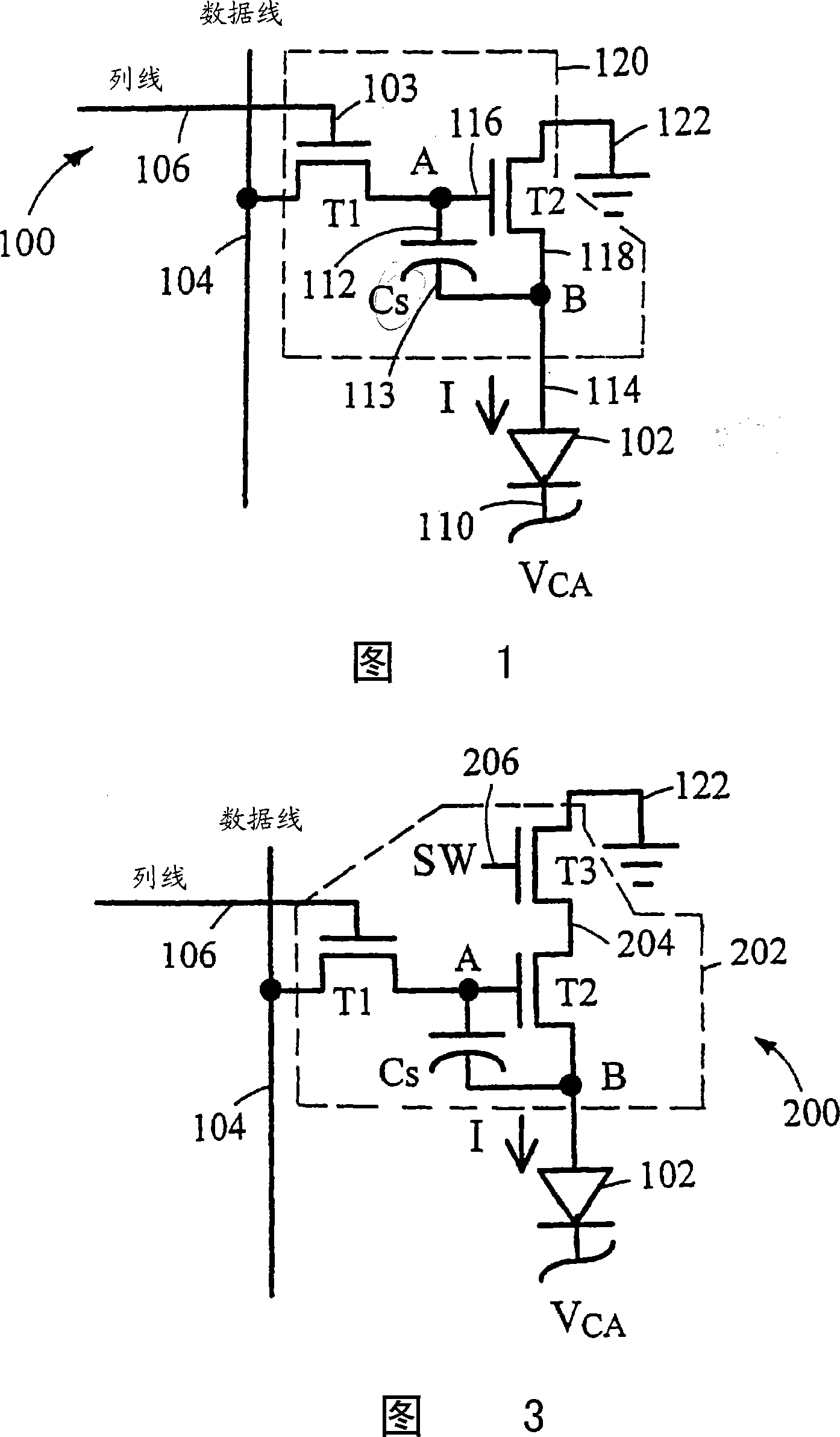
[0044] Please refer to FIG. 1 , which shows a circuit diagram of a display pixel according to a preferred embodiment of the present invention. The active matrix OLED pixel circuit 100 includes an OLED 102 for emitting light, which is a pixel (Pixel) seen by the user on the active matrix display 700 (as shown in FIG. 28 ). The brightness of the light emitted by the OLED102 is determined by the current I flowing through the OLED102 provided by the NMOS drive transistor T2, and the current I is determined by the threshold voltage greater than the transistor T2 (V TH2 ) of the gate-source voltage difference. The threshold voltage of transistor T2 will change over time under repeated use of the display. The pixel circuit 100 includes a storage capacitor C S , used to store the voltage of the control transistor T2. And the NMOS transistor T1 is connected to the capacitor C S and a data line (Data Line) 104 . In addition, the data line 104 provides a data voltage (V DATA ). Th...


PUM


Abstract

A pixel circuit includes a light emitting device, a storage device configured to represent a level of illumination, and a driving device used to drive the light emitting device. Configuring the storage device includes changing a voltage difference across the storage device to a level larger than a threshold voltage of the driving device. The driving device reduces driving of the light emitting device while the storage device is being configured. After the storage device has been configured, the driving device is permitted to drive the light emitting device to emit light having a luminance level corresponding to the level of illumination represented by the storage device.

Description

[0001] This application is a divisional application of the invention patent application with the application number "200410008277.5" and the invention title "display and its driving method and device" submitted by the applicant on March 2, 2004. technical field [0002] The present invention relates to a driving circuit of a display, and in particular to a pixel circuit (Pixel Circuit) of a display. Background technique [0003] Generally, an active matrix organic light emitting diode (Organic Light Emitting Diode; OLED) display includes a pixel circuit array forming a pixel row (Row) and a pixel column (Column) of the display. Each pixel circuit includes an OLED controlled by an active device such as a driving transistor. The OLED includes a luminescent substance that emits light when an electric current is introduced. The pixel circuit includes a storage capacitor for storing a voltage corresponding to the required brightness of the pixel. The drive transistor supplies t...

Claims


Application Information

Patent Timeline
Patent Type & Authority Applications(China)
IPC IPC(8): G09G3/30G09G3/32G09G5/10H05B33/08H05B33/14H05B37/02H01L51/50G09G3/20G09G5/00H01L27/12H01L27/32H01L29/786H05B44/00
CPCH01L27/3244H01L29/78648H01L29/78645G09G2320/043G09G2300/0847G09G3/3233G09G2300/0866G09G2300/0842G09G2300/0819H01L27/12H10K59/12
Inventor 詹姆士·L·山佛法兰克·R·里许
Owner INNOLUX CORP
Why Eureka
Try Eureka