Fixing device of battery

A fixing device and battery technology, which is applied to battery pack parts, circuits, electrical components, etc., can solve the problems of the battery cover 3a being difficult to cover, increase the manufacturing process, increase the production cost, etc., and achieve easy use, cost reduction, pre- The effect of increasing the pressure stroke

Inactive Publication Date: 2008-03-05
ALTEK CORP
View PDF0 Cites 3 Cited by
  • Summary
  • Abstract
  • Description
  • Claims
  • Application Information

AI Technical Summary

Problems solved by technology

[0004] However, in the above-mentioned known fixing device, the sponge 6a increases the closing force of the battery cover 3a, making it difficult to cover the battery cover 3a, and adding the sponge 6a to the battery seat 1a will increase the manufacturing process and increase the production cost.

Method used


Image

  • Fixing device of battery
  • Fixing device of battery

Examples


Embodiment Construction

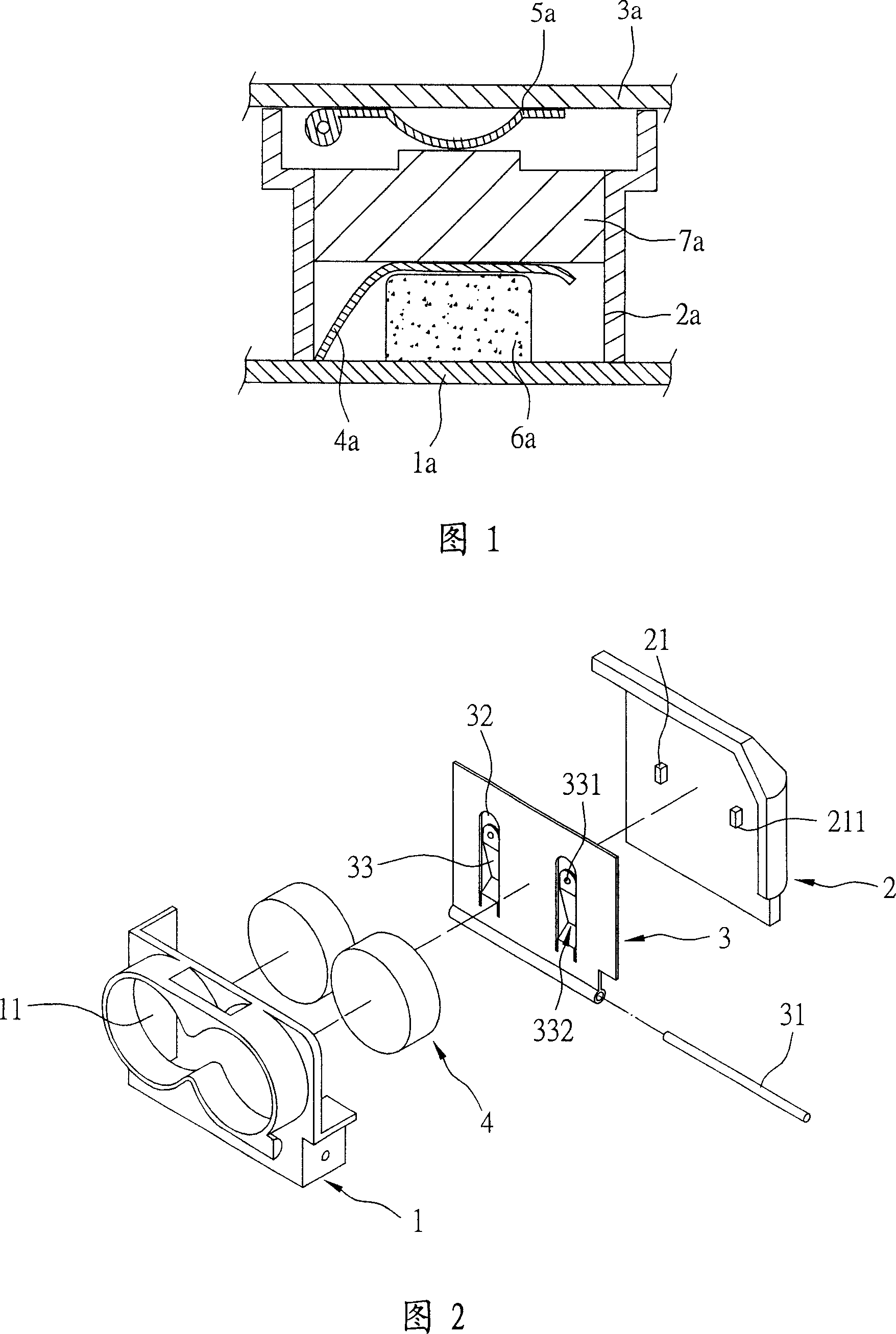
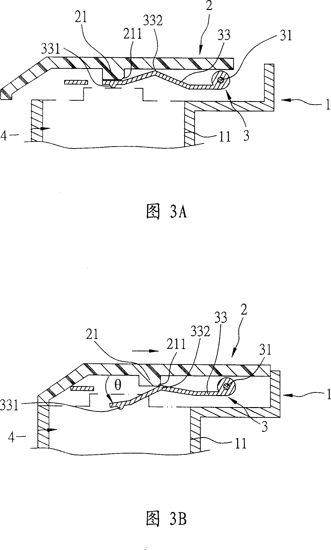
[0036] Please refer to FIG. 2 , FIG. 3A and FIG. 3B , the present invention provides a battery fixing device, which can be installed on an electronic device. The fixing device includes a bracket 1 , a shielding cover 2 and a battery spring 3 .

[0037] The bracket 1 is made of insulating material, and an accommodating space 11 with openings at both ends is formed inside the bracket 1. The accommodating space 11 and the bottom of the bracket 1 are connected to a battery holder (not shown in the figure), and in the accommodating space 11 The second battery 4 is accommodated, and the electrodes at the bottom of the second battery 4 are in contact with the shrapnel of the battery seat (not shown) to form an electrical connection.

[0038] The shielding cover body 2 is slidably assembled on the top of the bracket 1, and the shielding cover body 2 is provided with two square elastic spring shifting blocks 21, and the two elastic spring shifting blocks 21 are integrally formed with th...


PUM


Abstract

This invention relates to a fixing device for cells including a frame, a shield cover and at least one battery spring leaf and a dial block, in which, the frame contains cells, said shield cover can joint to the frame in slide, the leaf is set between the frame and the shield cover and set with an elastic arm including a pressing part and a contact part, thus, a fixing part of cells is formed, in which, when said shield cover slides and joints into the frame, said dial block of the leaf presses the press part to increase the pre-pressure journey of the elastic arm so as to avoid off power caused by weaving of the cells.

Description

technical field [0001] The invention relates to a fixing device for a battery, in particular to a fixing device which is arranged on an electronic device and can avoid power failure caused by shaking of the battery. Background technique [0002] The battery fixing devices of general electronic devices usually use contact springs to contact the electrodes at the upper and lower ends of the battery to achieve electrical connection. The itinerary also varies. When the height of the battery used is low, it is easy to cause the battery electrode to break away from the contact shrapnel instantly due to shaking. If the time of separation exceeds the time allowed by the circuit, the product will be powered off. [0003] In order to avoid the above situation, sponge is attached to the battery holder to increase the pre-pressing stroke of the contact shrapnel. As shown in Figure 1, the known battery fixing device includes a battery holder 1a, a bracket 2a, and a battery cover 3a , O...

Claims


Application Information

Patent Timeline
Patent Type & Authority Applications(China)
IPC IPC(8): H01M2/10H01M50/242H01M50/244H01M50/271
CPCY02E60/12Y02E60/10
Inventor 黄毓承林资智
Owner ALTEK CORP
Why Eureka
Try Eureka