Switching device for on-off switching of current through a current path

A switch device and current path technology, applied in the direction of electric switches, circuits, protection switches, etc., can solve the problems of large moving mass, long disconnection time, and inability to safely disconnect short circuits, etc., and achieve the effect of saving space and saving mechanisms

Active Publication Date: 2019-07-26
EATON INTELLIGENT POWER LIMITED
View PDF6 Cites 0 Cited by
  • Summary
  • Abstract
  • Description
  • Claims
  • Application Information

AI Technical Summary

Problems solved by technology

[0004] Electromagnetic drives for switching on and off have the disadvantage that they have a relatively large moving mass, which is necessary for the switching process
However, th...

Method used


Image

  • Switching device for on-off switching of current through a current path
  • Switching device for on-off switching of current through a current path
  • Switching device for on-off switching of current through a current path

Examples


Embodiment Construction

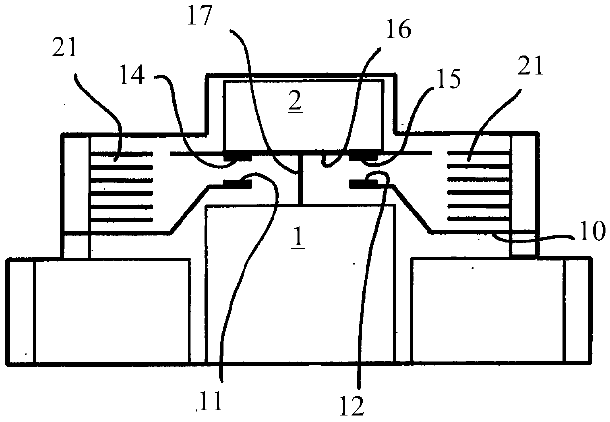
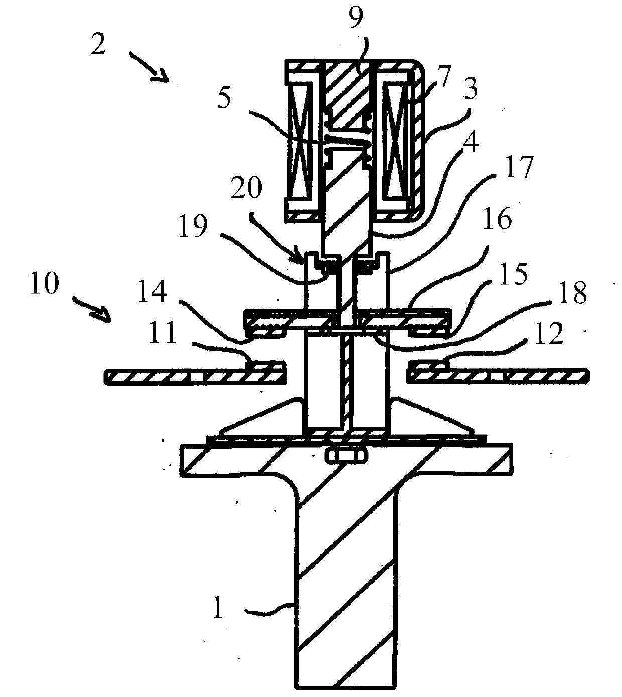
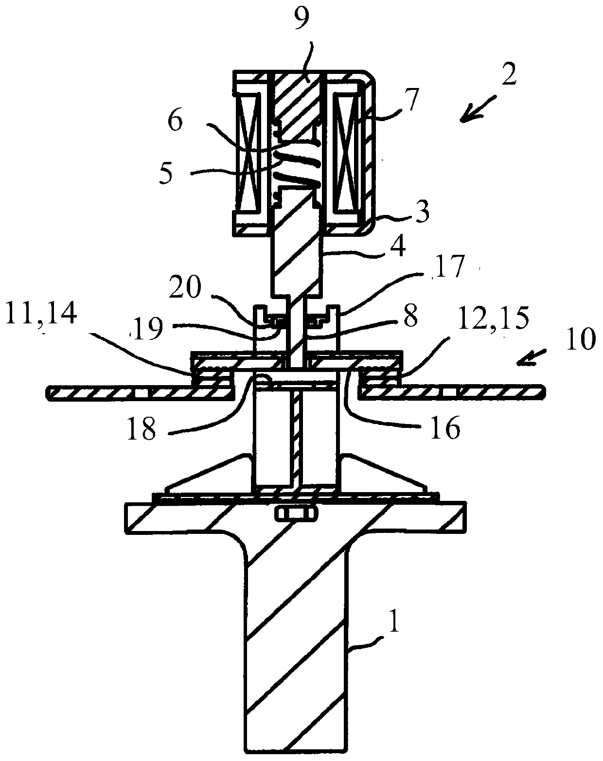
[0024] for example, figure 1 is a simplified schematic diagram of a switching device according to the invention with structure. For this reason, the switchgear used for the on-off switching of the current through the current path 10 has two static contacts 11,12, the two static contacts 11,12 are connected with the two moving contacts 14 on the moving contact bracket 16 , 15 cooperate to form and break the current path 10. The electromagnetic drive 1 is used for the movement of the jumper 17 between the contact making position and the contact breaking position, the moving contact carrier 16 is guided by the jumper 17 which will be discussed in more detail in connection with the following figures. The high-speed circuit breaker 2 for opening the current path 10 in the event of a short circuit or overload is also only schematically shown, and the detailed structure and function will be described in more detail below with reference to the drawings. Opening the short circuit req...


PUM


Abstract

The invention relates to a switching device for on-off switching of a current through a current path, which has at least one stationary contact (11, 12) and at least one moving contact (14, 15), wherein the moving contact The head is movable relative to said stationary contact to make or break said current path (10) and for functional movement of a jumper (17) between a contact making position and a contact breaking position A driver (1), wherein, in said contact forming position, said moving contacts (14, 15) and said stationary contacts form said current path and have means for opening said current path in the event of a short circuit or overload A high-speed circuit breaker (2) for the current path, wherein the armature (4) of the high-speed circuit breaker (2) is rigidly coupled to the moving contacts (14, 15).

Description

technical field [0001] The invention relates to a switching device for switching on and off a current passing through a current path, which has at least one stationary contact and at least one moving contact, wherein the moving contact is movable relative to the stationary contact to form and break open current path, with a drive for the movement of the jumper between the contact making position and the contact breaking position, wherein, in the contact making position, the fixed contact, the moving contact form the current path, and with a drive for the short circuit Or a high-speed circuit breaker that interrupts the current path in the event of an overload. Background technique [0002] Switching devices of this type are used, for example, in motor starters with corresponding, usually electromagnetic drives. These are suitable for functional switching of loads, disconnection of overloads and disconnection in case of short circuit. Basically, two separate switching devic...

Claims


Application Information

Patent Timeline
IPC IPC(8): H01H50/54H01H71/24H01H89/08
CPCH01H50/546H01H71/2463H01H89/08H01H1/20H01H1/2008
Inventor V·朗
Owner EATON INTELLIGENT POWER LIMITED
Why Eureka
Try Eureka