Heat shield with ceramic fiber structure

A technology of ceramic fiber and heat shield, which is used in electromechanical devices, electrical components, liquid fuel engines, etc., can solve the problem that the low-pressure cooling water circulation structure cannot be realized, it is difficult to cast internal water holes, and it is easy to form air holes and slag holes, etc. problems, to achieve a wide range of applications, save maintenance costs, reduce heat transfer effects

Pending Publication Date: 2021-09-21
HARBIN ELECTRIC POWER EQUIP
View PDF13 Cites 0 Cited by
  • Summary
  • Abstract
  • Description
  • Claims
  • Application Information

AI Technical Summary

Problems solved by technology

[0002] The furnace water pump motor is separated from the pump casing by a heat shield. The pump casing and the motor are divided into two equal-pressure chambers of 22MPa. The heat shield also bears the same pressure. The temperature of the high-temperature furnace water in the pump casing is about 300°C. , the operating temperature of the motor is below 60°C, the high-temperature furnace water in the pump casing does not exchange with the water in the inner cavity of the motor, that is, there is only heat conduction but no heat cycle, and the heat shield is a key component of the furnace water pump, which directly affects the performance of the motor. Whether it works normally, compared with the traditional casting heat shield, it is difficult to cast internal water holes, and the low-pressure cooling water circulation structure cannot be realized, and the heat insulation effect is poor. It is easy to leak under long-term operation. Once the high-temperature furnace water enters the motor, the motor winding will overheat instantly and the motor will not be able to run.

Method used


Image

  • Heat shield with ceramic fiber structure
  • Heat shield with ceramic fiber structure
  • Heat shield with ceramic fiber structure

Examples


Embodiment Construction

[0014] Amend the following in accordance with the amended claims

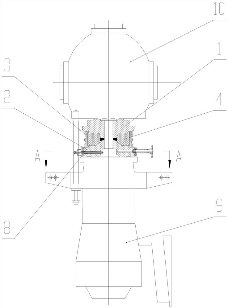
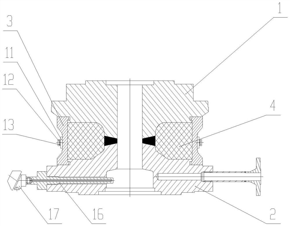
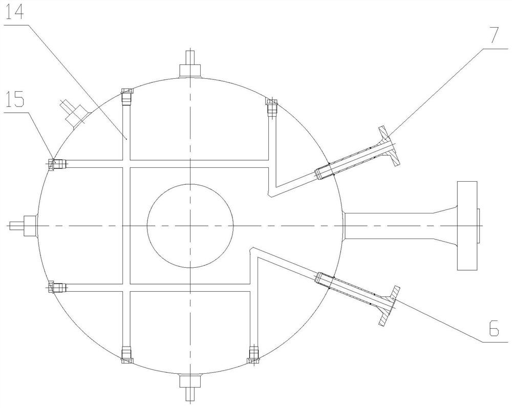
[0015] Such as figure 1 As shown, a heat shield with a ceramic fiber structure, the upper part 1 of the heat shield and the lower part 2 of the heat shield are welded and fixed together, and the outer edge of the upper part 1 of the heat shield and the lower part 2 of the heat shield is installed with a support ring 3 for heat insulation The cavity formed by the upper part 1 of the screen, the lower part 2 of the heat shield and the inner side of the support ring 3 is filled with ceramic fiber 4 heat insulation material. The two petals of the support ring 3 are fixed by bolts 12 and spring washers 13, and the lower part 2 of the heat shield has a plurality of low-pressure internal water holes 14 interconnected with each other, such as image 3 As shown, the low-pressure internal water hole 14 is externally blocked with a screw plug 15, and there are low-pressure cooling water inlet pipes 6 and outlet pipes 7 i...


PUM


Abstract

The invention designs a heat shield with a ceramic fiber structure. A heat shield upper portion (1) and a heat shield lower portion (2) are welded and fixed together, a supporting ring (3) is installed on the outer edge between the heat shield upper portion (1) and the heat shield lower portion (2), an inner cavity formed by the heat shield upper portion (1), the heat shield lower portion (2) and the inner side of the supporting ring (3) is filled with ceramic fiber (4) heat insulation materials, and the supporting ring (3) is of a two-section structure. The two sections of the supporting ring (3) are connected through a connecting plate (11). Due to the specific characteristics of high temperature resistance, low heat conductivity coefficient and the like of the ceramic fibers, heat transfer is reduced, high-temperature boiler water in the pump shell can be effectively separated from water in a motor cavity, the heat insulation screen effectively insulates heat, the influence of the high-temperature boiler water on motor operation is avoided, the operation safety is improved, the failure rate is reduced, and the maintenance cost is saved. The heat shield is wide in application range, and is applicable to heat insulation of a water pump motor shell and a motor of a supercritical and supercritical furnace without air cooling in an indoor power station.

Description

Technical field: [0001] The invention relates to a ceramic fiber structure heat shield. Background technique: [0002] The furnace water pump motor is separated from the pump casing by a heat shield. The pump casing and the motor are divided into two equal-pressure chambers of 22MPa. The heat shield also bears the same pressure. The temperature of the high-temperature furnace water in the pump casing is about 300°C. , the operating temperature of the motor is below 60°C, the high-temperature furnace water in the pump casing does not exchange with the water in the inner cavity of the motor, that is, there is only heat conduction but no heat cycle, and the heat shield is a key component of the furnace water pump, which directly affects the performance of the motor. Whether it works normally, compared with the traditional casting heat shield, it is difficult to cast internal water holes, and the low-pressure cooling water circulation structure cannot be realized, and the heat i...

Claims


Application Information

Patent Timeline
Patent Type & Authority Applications(China)
IPC IPC(8): F04B53/08F04B17/03H02K5/10
CPCF04B53/08F04B17/03H02K5/10
Inventor 杨凤君王勇张尧李函霖刘宇晨刘继东杨爽王策张韵曾
Owner HARBIN ELECTRIC POWER EQUIP
Why Eureka
Try Eureka