Eureka AIR delivers breakthrough ideas for toughest innovation challenges, trusted by R&D personnel around the world.

Load-bearing, lightweight, and compact super-insulation system

a super-insulation system and lightweight technology, applied in the direction of service pipe system, special purpose vessel, borehole/well accessories, etc., can solve the problems of high cost, high cost, difficult manufacturing, installation and maintenance, etc., and achieve high load-bearing capability, easy installation and maintenance, and high thermal-insulation performance.

Active Publication Date: 2005-03-03
ASPEN AEROGELS INC
View PDF15 Cites 27 Cited by
  • Summary
  • Abstract
  • Description
  • Claims
  • Application Information

AI Technical Summary

Benefits of technology

The thermal insulation systems of this disclosure can be used for such diverse applications as deep-water pipeline insulation, LNG tanker insulation, process piping, etc. These systems insulation systems can be characterized as follows: lightweight, thin, low-cost, high thermal-insulation performance and high load-bearing capability, as well as being easily installed and maintained. Pre-existing insulation systems may satisfy some of the above desired properties but not all of them. For example, evacuated multiple layer insulation (MLI) encased in heavy metal frames performs marvelously in terms of load-bearing capability and thermal performance; but, in general, MLI's are extremely heavy and expensive and are very difficult to manufacture, install and maintain. On the other hand, low-density silica aerogels offer excellent insulation with up to five times the thermal-insulation performance of commonly used fiberglass in ambient conditions, though the low-density aerogels typically cannot support the load beyond a fraction of an atmosphere before getting compressed. Fiberglass is cheap, but it is too bulky and ineffective; moreover, fiberglass is non-load-bearing, and its installation is messy. Foam can be load-bearing to a very limited extent, and the thermal-insulation performance is too low.
When designed for a given set of operating conditions, the new design can offer the following advantages and salient features over the state-of-the-art: (a) a much thinner (by nearly an order of magnitude) wall of the outer skin; (b) a much smaller carrier-pipe outer diameter; (c) a drastically reduced total weight (reduced by close to one half that of the conventional design); (d) a higher flexibility and a tighter bending radius (approaching that of the inner pipe alone in the state-of-the art or GRP pipe-in-pipe design); (e) more effective thermal insulation between the underlying structure and the outer skin; (f) a lower material and fabrication cost; (g) a smaller spool diameter or fewer spools for the same length of a pipe-in-pipe installation; and (h) a lower installation and maintenance cost, etc. Additionally, pipe-in-pipe designs of this disclosure are eminently suitable for automated fabrication in mass scale to drastically reduce the labor cost and therefore reduce the total cost of the pipe-in-pipe apparatus. Further still, fewer trips to the installation site need be made to carry the same length of pipe-in-pipe apparatus for spool or J-lay installation.

Problems solved by technology

Pre-existing insulation systems may satisfy some of the above desired properties but not all of them.
For example, evacuated multiple layer insulation (MLI) encased in heavy metal frames performs marvelously in terms of load-bearing capability and thermal performance; but, in general, MLI's are extremely heavy and expensive and are very difficult to manufacture, install and maintain.
Fiberglass is cheap, but it is too bulky and ineffective; moreover, fiberglass is non-load-bearing, and its installation is messy.
Foam can be load-bearing to a very limited extent, and the thermal-insulation performance is too low.

Method used


Image

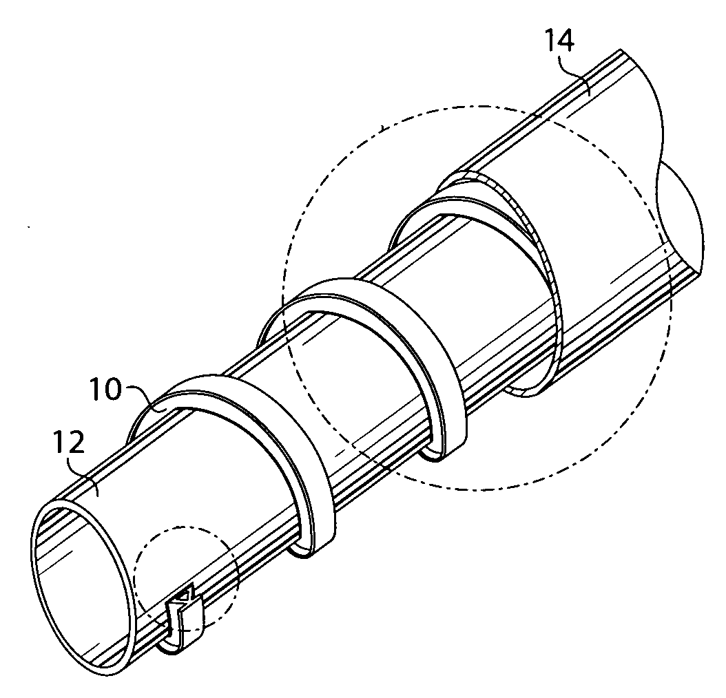
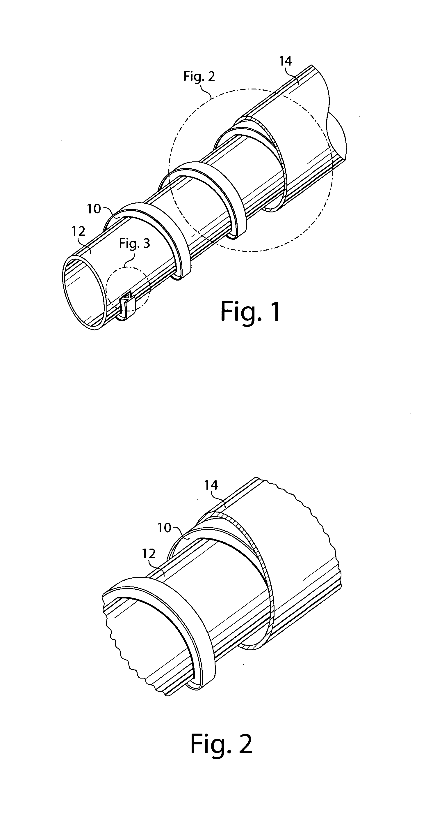
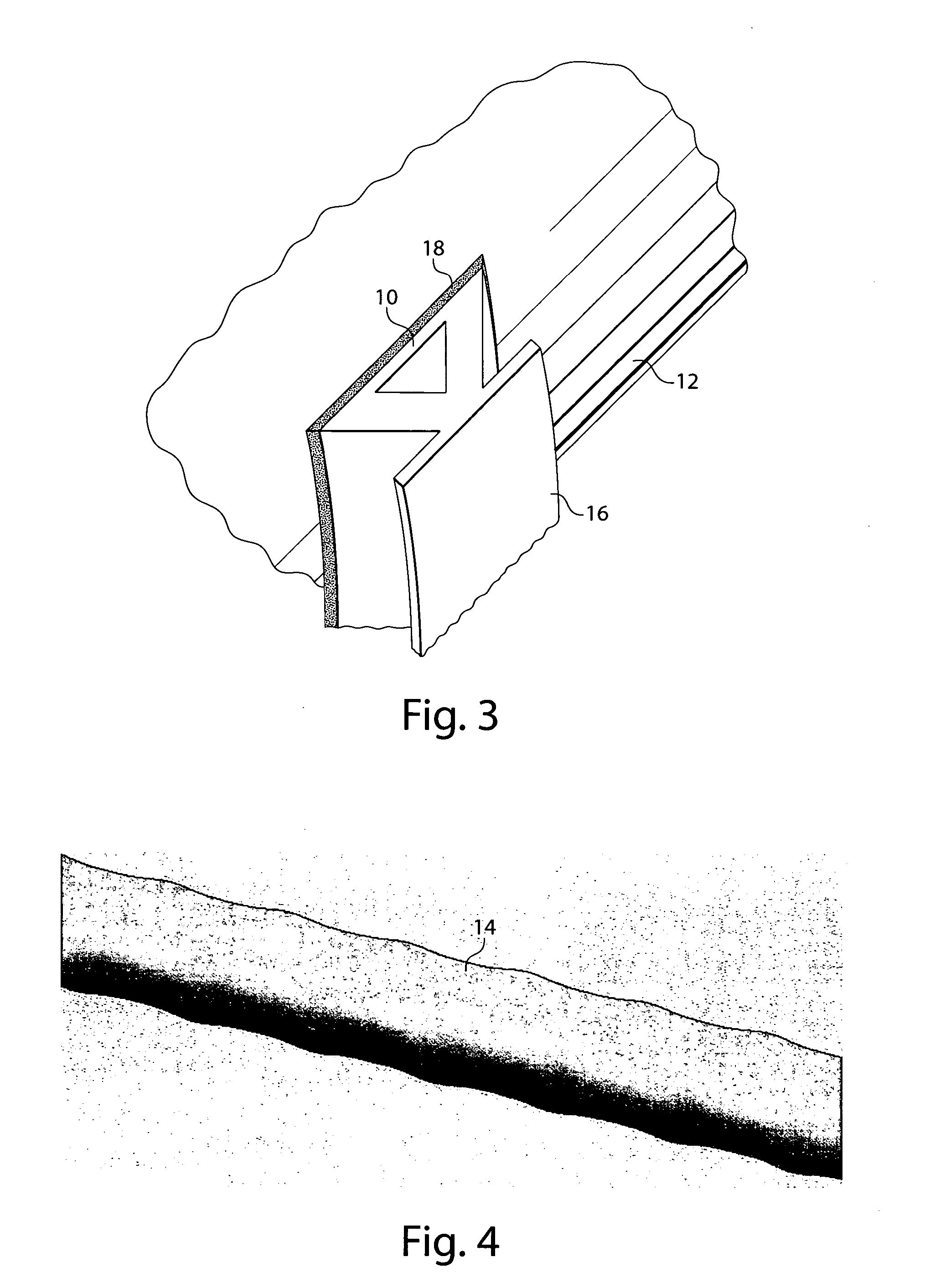
  • Load-bearing, lightweight, and compact super-insulation system
  • Load-bearing, lightweight, and compact super-insulation system
  • Load-bearing, lightweight, and compact super-insulation system

Examples


Embodiment Construction

Traditional pipe-in-pipe designs, and even the recent GRP design, rely on the outer carrier pipe having sufficient thickness and strength to handle the external load on its own without collapsing under normal operating conditions. By necessity, this makes the outer wall of the carrier pipe relatively thick.

When a pipe is exposed to an external pressure, q, the failure mode ordinarily is that of pipe collapse due to elastic buckling instability under compressive load, which is approximately given by: q=14*E1-v2*t3r3(Eqn. ⁢1)

(Warren C. Young, Formulas for Elastic Stability of Plates and Shells, Roark's Formulas for Stress and Strain, Sixth Edition, McGraw-Hill, Inc., Equation 19.a, Table 35, 1989), where q is the external pressure; E is Young's Modulus; v is Poisson's Ratio; t is the wall thickness; and r is the mean radius. For a long tube held circular at intervals of l, q=0.807*El*t2r⁢(11-v2)3*t2r24(Eqn. ⁢2)

(Warren C. Young, Formulas for Elastic Stability of Plates and Shell...


PUM


Abstract

A lightweight and compact super-insulation system that is also capable of supporting a high level of compressive load is described. The system utilizes spacers to provide structural support and utilize controlled buckling of a thin protective outer skin supported by spacers to form strong catenary surfaces to protect insulation material underneath. The spacers may comprise an aerogel, or an aerogel may provide insulation separate from the spacer yet contained within the thin outer skin. The system will be useful for thermal management of variety of deep underwater structures such as pipe-in-pipe apparatus, risers or subsea trees for ultra-deep water oil-and-gas exploration.

Description

BACKGROUND In deep- and ultra-deep-water oil and gas exploration, crude oil or gas is extracted from below the sea floor via a pipeline system to the water surface. It is important to maintain the temperature of the hot crude oil or gas flowing in the pipe above about 30-50° C. depending on the composition of the hydrocarbons (e.g., crude oil or natural gas). Maintaining a temperature in this range prevents flow restrictions or clogging due to formation of hydrates or wax, which can occur via cooling of the crude oil or gas by cold water as the hydrocarbons flow from the underwater well to the production plant on the surface. Also, if the well must be capped for maintenance or due to inclement weather, it is highly desired to keep the temperature of the hydrocarbon inside the pipe and other parts of the pipeline systems (e.g., a Christmas tree or subsea tree, risers, etc.) above precipitation temperature for as long as possible to minimize or avoid expensive and time-consuming de-c...

Claims


Application Information

Patent Timeline
Patent Type & Authority Applications(United States)
IPC IPC(8): F16L59/125F16L59/14
CPCF16L59/143F16L59/125E21B43/013E21B43/01
Inventor LEE, KANGLEESER, DANIEL LOUISKRAJEWSKI, MARK
Owner ASPEN AEROGELS INC
Why Eureka
Eureka Blog
Learn More