Dynamic balancing lock pin

A technology of lock cylinder and outer lock cylinder, which is used in locks with turning keys, construction locks, cylinder pin locks, etc. Effect

Active Publication Date: 2008-03-12
李咸恭
View PDF0 Cites 0 Cited by
  • Summary
  • Abstract
  • Description
  • Claims
  • Application Information

AI Technical Summary

Problems solved by technology

Therefore, the safety and anti-theft performance of these marbles or blade locks are not ideal

Method used


Image

  • Dynamic balancing lock pin
  • Dynamic balancing lock pin
  • Dynamic balancing lock pin

Examples


Embodiment Construction

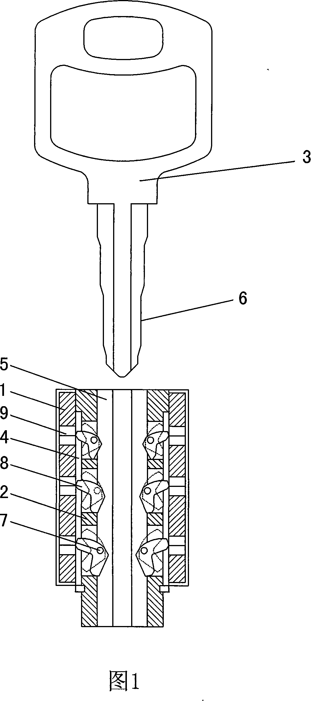
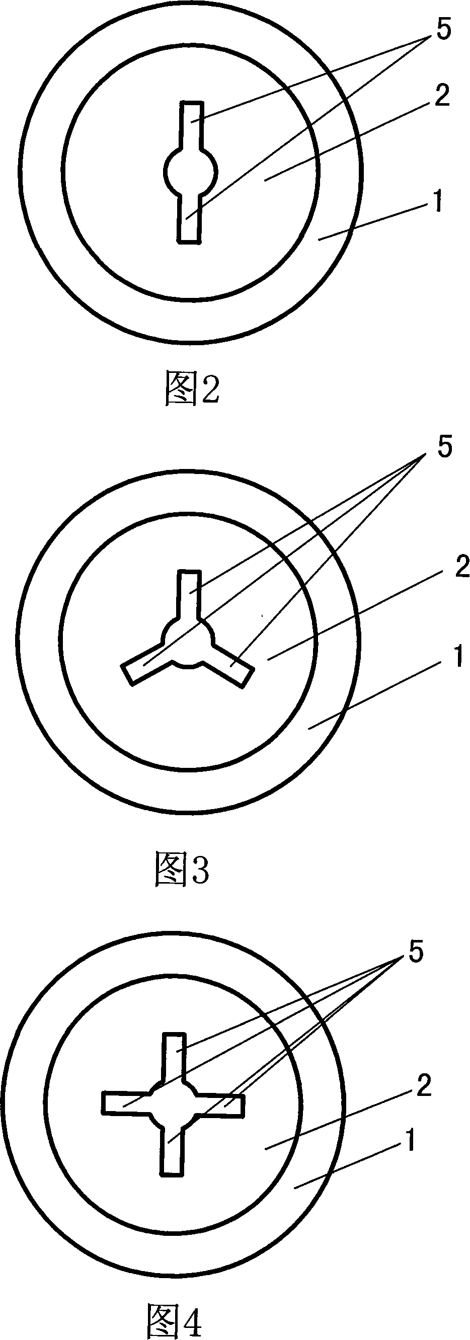
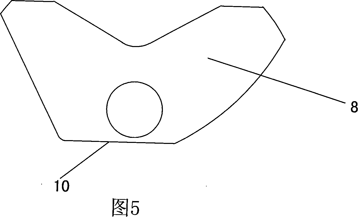
[0017] Referring to Fig. 1 and Fig. 2, a dynamic balance lock cylinder disclosed by the present invention includes an outer lock cylinder 1, an inner lock cylinder 2 and a key 3 set in the outer lock cylinder 1, and two grooves are arranged in the outer lock cylinder 1 4. Two long grooves 5 are arranged in the inner lock cylinder 2, and three dynamic balance bolts 8 are connected to the long grooves 5 through the rotating shaft 7 in turn, and can rotate freely in the long grooves 5.

[0018] Several magnets 9 are installed in the outer lock cylinder 1, and each magnet 9 corresponds to one end of a dynamic balance bolt 8. The dynamic balance bolt 8 is made of high-strength magnetic metal material. When the lock core is in the locked state, the dynamic balance bolt One end of 8 is inserted in the groove 4 of the outer lock core 1 under the action of the magnetic force of the magnet 9, thereby locking the inner and outer lock cores. Of course, the dynamic balance bolt 8 can also ...


PUM


Abstract

The invention discloses a dynamic balance lock core that comprises an external lock core, an internal lock core sleeved inside the external lock core and keys. The invention is characterized in that the external lock core inside is arranged with a groove; the internal lock core inside is arranged with a long groove; the long groove inside is arranged with a plurality of dynamic balance latches; the latches can be fixed in sequence inside the long groove on the internal lock core through a rotary shaft, and meanwhile, rotated inside the long groove; when the lock core is in a latched status, one end of the dynamic balance latch is plugged into the groove inside the external lock core; when a key is plugged in to unlock the lock core, convex parts on both ends of the dynamic balance latch are positioned on a boundary between the internal and external lock cores. The invention adopts a dynamic balance latch to substitute prior bullets or vanes in locking the internal and external lock cores, so that the lock is characterized by high unlocking difficultites and high resistance against violent damages.

Description

technical field [0001] The invention relates to a lock core, in particular to a lock core in which a dynamic balance bolt with high strength, high anti-theft performance and simple manufacture replaces the existing pins or blades. Background technique [0002] Looking at all the locks currently on the market, whether it is a high-tech product integrating sound, light, mechanics, and electricity, or the most common and most frequently used pin lock or blade lock, in the increasingly advanced technical unlocking means or In the face of violent and destructive unlocking methods, its preventive ability is getting smaller and smaller. For example, for electronic locks, electronic technology can be used to open them, or they can be destroyed by strong magnetism and high temperature. For pin locks or blade locks, no matter whether the structure of the lock cylinder is simple or complex, there are rules to follow, and it is easy to unlock within a few seconds to a few minutes by te...

Claims


Application Information

Patent Timeline
Patent Type & Authority Applications(China)
IPC IPC(8): E05B27/08E05B15/16
Inventor 李明
Owner 李咸恭
Why Eureka
Try Eureka