An anti-filling spool and valve

An anti-filling and valve core technology, applied in the field of valve cores, can solve the problems of low reliability of anti-filling, easy to break the static equilibrium state of the opening limit, etc., so as to improve the safety of anti-filling, improve the opening difficulty, The effect of improving work reliability

Active Publication Date: 2016-04-20
深圳市知合物联通信技术有限责任公司
View PDF6 Cites 0 Cited by
  • Summary
  • Abstract
  • Description
  • Claims
  • Application Information

AI Technical Summary

Problems solved by technology

[0007] One of the technical problems to be solved by the present invention is to provide an anti-filling spool, which overcomes the defects of the existing anti-filling spool that the static equilibrium state of the opening limit is easily broken and the reliability of the anti-filling is low.
[0008] The second technical problem to be solved by the present invention is to provide a valve that uses the above-mentioned anti-filling valve core to overcome that the static equilibrium state of the opening limit of the existing valve anti-filling valve core is easily broken and the anti-filling reliability is low. Defects

Method used


Image

  • An anti-filling spool and valve
  • An anti-filling spool and valve
  • An anti-filling spool and valve

Examples


Embodiment Construction

[0051] The present invention will be further described below in conjunction with the accompanying drawings and embodiments.

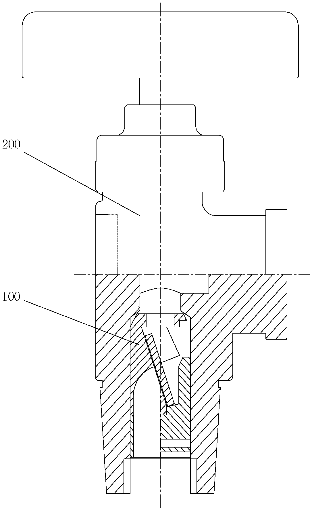
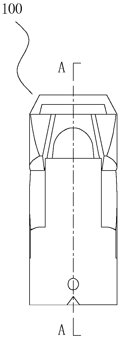
[0052] Such as Figure 7 to Figure 11 As shown, the anti-filling valve core 300 of the present invention includes an upper valve core 310, a lower valve core 330, a sail plate 320, a through filling gas through hole arranged on the upper valve core and the lower valve core, and a The sail chamber 340 between the spool 310 and the lower spool 330 .

[0053] The lower spool 330 includes an outer surface (such as Figure 14 As shown), it has been ensured that the filling gas is filled into the steel cylinder through the filling gas hole of the valve core.

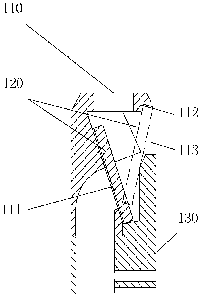
[0054] The sail chamber 340 includes a spool slope 317 arranged along the slant direction of the spool axis N, a spool top 316 located on the top of the upper valve body 310, and the outer surface of the spool top 316 is tightly fitted with the spool cavity wall ( like Figure 14 As shown), it has b...


PUM


Abstract

Provided is a filling prevention valve element and a valve. The valve element comprises an upper valve element body, a lower element body, a turning plate, a gas filling through hole penetrating through the upper valve element body and the lower valve element body and a turning plate cavity formed between the upper valve element body and the lower valve element body; the outer surface of the lower valve element body is matched with the wall of a valve element cavity of a valve body in an airtight mode; the turning plate cavity is provided with a valve element slope in the oblique direction of the axial direction of the valve element, the top of the turning plate cavity is a valve element top of an upper valve body, and the outer surface of the valve element top is matched with the wall of the valve element cavity in an airtight mode; the gas filling through hole comprises a top hole in the valve element top and a bottom hole penetrating through the lower valve element body or penetrating through the upper valve element body and the lower valve element body, and an upper port of the bottom hole is arranged on the valve element slope; the turning plate can rotate around the lower end of the turning plate cavity freely, and the working surface of the turning plate is matched with the upper port of the bottom hole to block the bottom hole; the vertical turning plate can be completely contained in a shelter area which is formed by the area, where the projection of the part between the edge, right facing the valve element slope, of the top hole and the inner edge where the valve element top is located in the turning plate cavity passes through downwards in the axial direction of the valve element, of the turning plate cavity. The valve comprises the valve body and the valve element installed in the valve element cavity of the valve body. Safety filling reliability of the valve is improved.

Description

technical field [0001] The invention relates to a valve core used for an anti-filling structure of a pressure container valve, and also relates to a valve using the valve core. Background technique [0002] figure 1 Shown is a valve used on a liquefied petroleum gas cylinder, including a valve body 200 and a valve core 100 installed in the valve core chamber of the valve body 200 . Such as Figure 2 to Figure 6 As shown, the traditional anti-filling spool 100 includes an upper spool 110, a lower spool 130, a sail plate 120 and a filling gas through hole arranged on the upper spool 110 and the lower spool 130; The outer sides of the core 110 and the lower valve core 130 are airtightly matched with the valve core chamber wall of the valve body 200; a sail board cavity is set between the upper valve core 110 and the lower valve core 130, and the sail board 120 can rotate freely in the sail board cavity. ; On the upper valve core 110 in the sail board cavity, an inclined slop...

Claims


Application Information

Patent Timeline
Patent Type & Authority Patents(China)
IPC IPC(8): F16K17/00
CPCF16K1/30F17C13/04
Inventor 严灿
Owner 深圳市知合物联通信技术有限责任公司
Why Eureka
Try Eureka