Panel lighting test machine and detecting method thereof

A testing machine and panel technology, which is applied in the direction of optical instrument testing, machine/structural component testing, electrical measurement, etc., can solve the problems of increasing the process time of lighting detection, etc., and achieve the effect of shortening the process conversion time and shortening the time

Active Publication Date: 2008-03-12
AU OPTRONICS CORP
View PDF0 Cites 34 Cited by
  • Summary
  • Abstract
  • Description
  • Claims
  • Application Information

AI Technical Summary

Problems solved by technology

Transferring panels back and forth and laser repair offset causi...

Method used


Image

  • Panel lighting test machine and detecting method thereof
  • Panel lighting test machine and detecting method thereof
  • Panel lighting test machine and detecting method thereof

Examples


Embodiment Construction

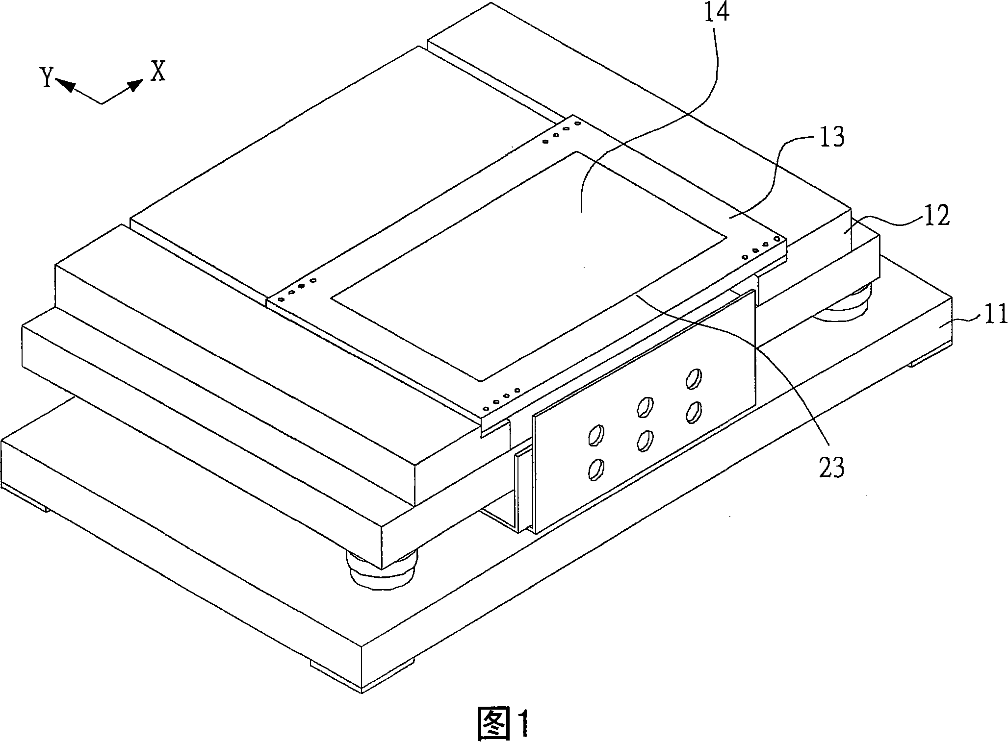
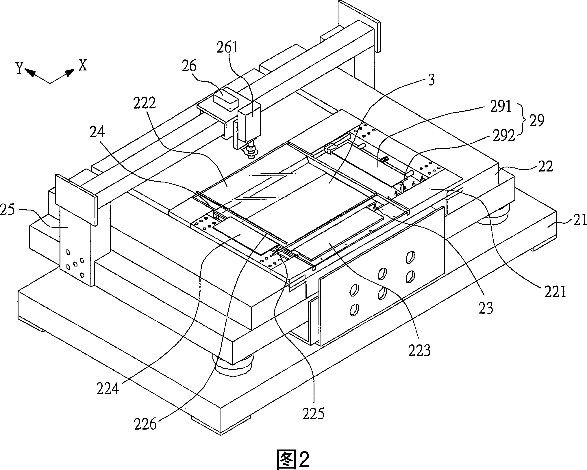
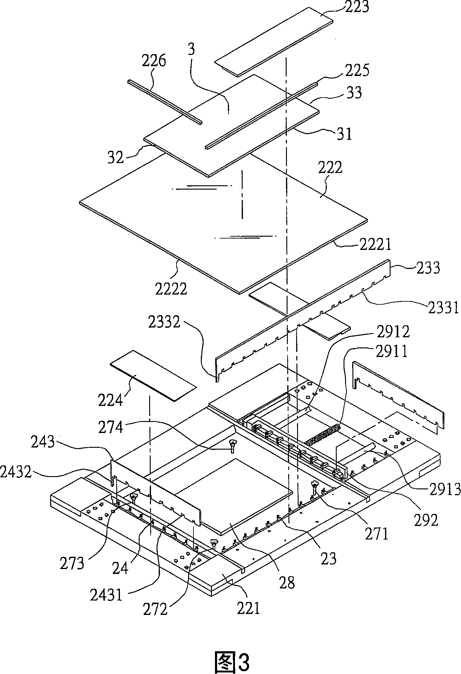
[0040] First, please refer to FIG. 2 and FIG. 3 , wherein FIG. 2 is a perspective view of a panel lighting tester according to an embodiment of the present invention, and FIG. 3 is an exploded view of a panel lighting tester according to an embodiment of the present invention. A panel lighting testing machine according to an embodiment of the present invention includes: a base 21 , a panel bearing seat 22 , a plurality of lighting testing parts 23 , 24 , a support frame 25 and a laser repair unit 26 . Wherein, the panel bearing seat 22 is disposed on the base 21 and reciprocates on the base 21 along the Y direction in FIG. 2 . In addition, the panel carrier 22 includes a rectangular frame body 221, a carrier plate 222 and a plurality of positioning units 223, 224, the carrier plate 222 is arranged on the rectangular frame body 221, and the plurality of positioning units 223, 224 are respectively arranged on the sides of the carrier plate 222. Two sides 2221,2222. In this embo...


PUM


Abstract

The invention discloses a testing machine for panel lighting and its method of detection, used for lighting testing and panel repairing, which comprises a base, a panel bearing base, a plurality of lighting testing units, a support stand and a laser repair unit. The panel bearing base, composed of a rectangular frame, a bearing board and a plurality of positioning units, is amounted on the base. The bearing board is equipped on the rectangular frame and the said positioning units are set separately on the sides of the bearing board. The lighting testing units is installed on the medial side of the rectangular frame, consisting of a slide rail, a plurality of probe sliders and a positioning unit for the probe sliders. The said probe sliders with a plurality of probes are separately equipped on the slide rail. The said positioning unit for the probe sliders is provided with a plurality of grooves, in which the probe sliders are amounted to limit the location of the said probe sliders. On the other hand, the said support frame fitted with the laser repair unit is equipped on the upside of the base.

Description

technical field [0001] The invention relates to a panel lighting testing machine and a detection method thereof, in particular to a panel lighting testing machine which can effectively shorten the time required for panel repair procedures and can quickly and accurately adjust the position of its probe slider. Background technique [0002] Please refer to FIG. 1 , which is a perspective view of a known panel lighting tester. A known panel lighting testing machine includes: a base 11 , a panel bearing seat 12 , a panel fixing fixture 13 , and a plurality of lighting testing parts (not shown in the figure). Wherein, the panel bearing seat 12 is arranged on the base 11 and moves back and forth on the base 11 along the Y direction in FIG. In addition, the aforesaid multiple lighting test parts (not shown in the figure) are respectively arranged on the lower side of the panel fixing fixture 13 and respectively include a plurality of probe sliders (not shown in the figure), so as ...

Claims


Application Information

Patent Timeline
IPC IPC(8): G09G3/00G01R31/00G01M11/00
Inventor 刘铠瑜
Owner AU OPTRONICS CORP
Why Eureka
Try Eureka