Climbing cone type triangular cantilever bracket

A technology of cantilever brackets and triangular trusses, applied in the field of brackets, can solve problems such as difficulty in ensuring welding quality and safety of high-altitude operations, long time for bracket erection and dismantling, and affecting process transition time, etc., to shorten process transition time and improve construction efficiency High effect with little effect on appearance

Inactive Publication Date: 2015-01-07
GUANGDONG PROVINCIAL CHANGDA HIGHWAY ENG
View PDF8 Cites 0 Cited by
  • Summary
  • Abstract
  • Description
  • Claims
  • Application Information

AI Technical Summary

Problems solved by technology

[0003] The construction of the above-mentioned continuous rigid frame box girder mainly uses floor-standing steel pipe brackets or wooden brackets to support the cast-in-place box girder. This type of bracket has the following defects and deficiencies: 1. Large amount of materials used, low turnover efficiency, and material loss Large, especially the loss of the steel pipe is particularly large, which greatly increases the construction cost
2. It takes a long time to erect and dismantle the support, and the construction efficiency is low, which seriously affects the process conversion time
3. During the lapping process of this type of support, the welding requirements for on-site workers are high, and there are many high-altitude working surfaces, so it is difficult to guarantee the welding quality and operation safety during high-altitude operations

Method used


Image

  • Climbing cone type triangular cantilever bracket
  • Climbing cone type triangular cantilever bracket
  • Climbing cone type triangular cantilever bracket

Examples


Embodiment Construction

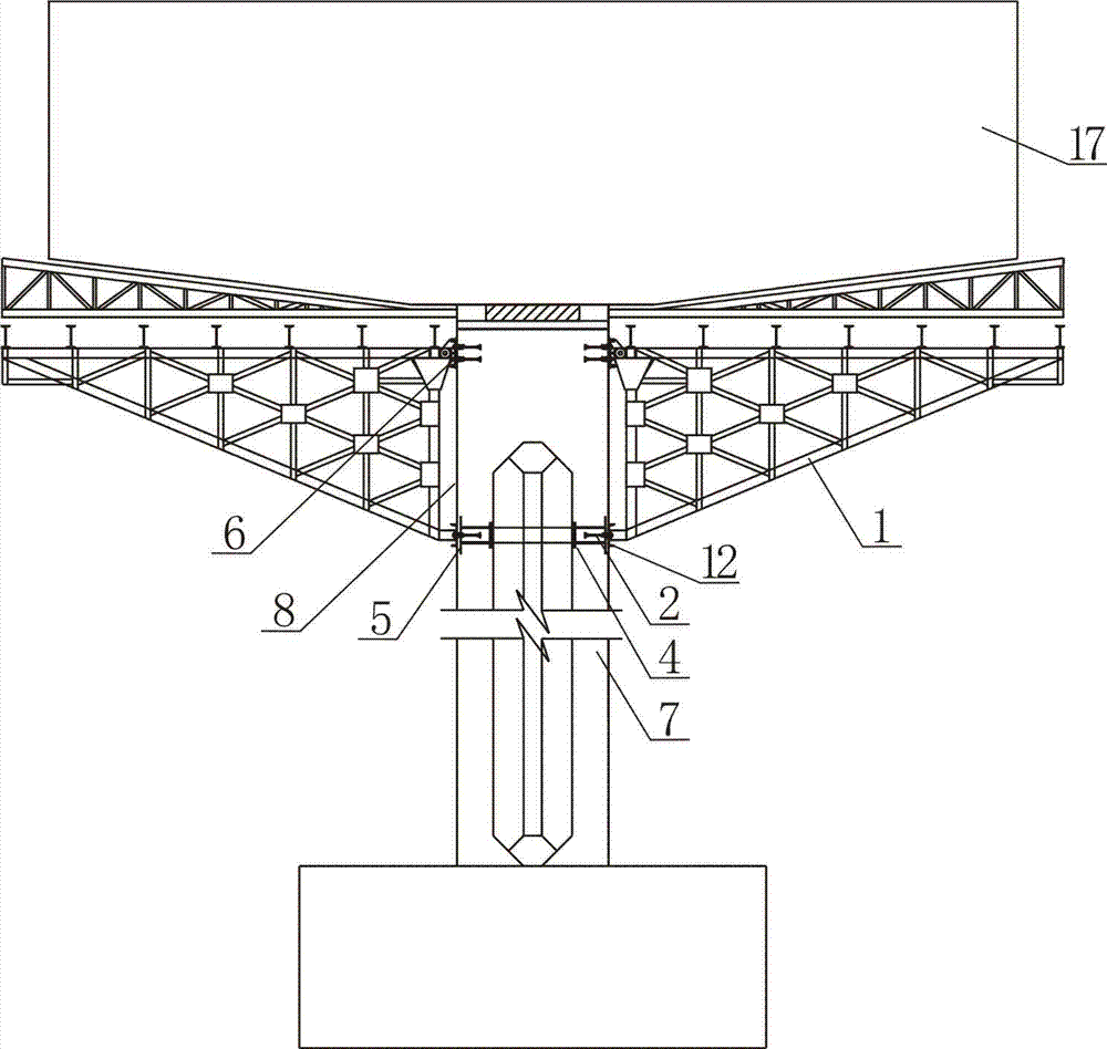
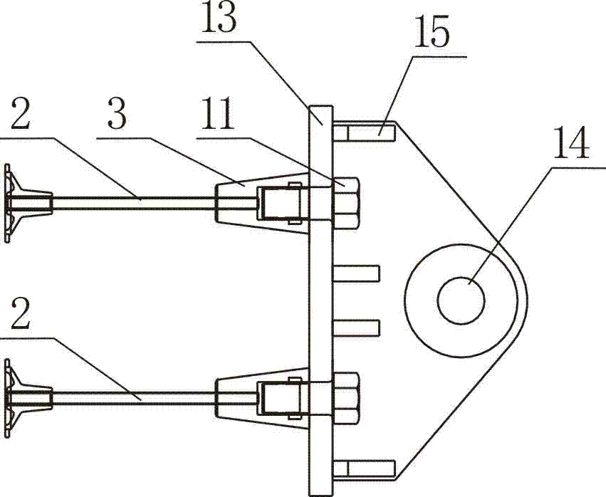
[0023] Such as figure 1 , 3 As shown in , 4, the climbing cone type triangular cantilever support is composed of a tripod 1, climbing cone bolts 2, conical nuts 3, steel plates 5, steel mesh 4 and fixing seats 6, and the climbing cone bolts 2 are embedded horizontally On the upper part of the pier body 7, the steel plate 5 is vertically pre-buried in the pier body 7 and close to the front end of the climbing cone bolt 2, the surface of the steel plate 5 is perpendicular to the climbing cone bolt 2, and the steel mesh 4 is arranged on the climbing cone bolt 2, the tapered nut 3 is pre-embedded in the pier body 7, one end is threaded with the front end of the climbing cone bolt 2, and the other end is flush with the side 8 of the pier body.

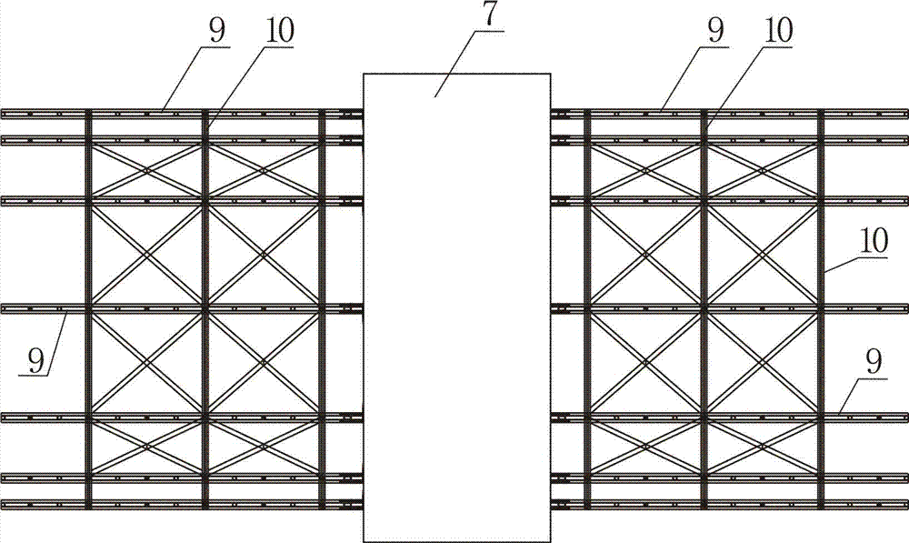
[0024] Such as figure 1 , 2 , 5, the tripod 1 is composed of 7 triangular trusses 9 and cross-links 10, the length of the right-angled side of the triangular truss is 300cm, and the length of the other right-angled side is 750cm. A plur...


PUM


Abstract

The invention discloses a climbing cone type triangular cantilever bracket which consists of a triangular bracket, a climbing cone bolt, a cone-shaped nut, a steel plate, a steel mesh and a permanent seat. The permanent seat is fixedly arranged on the side face of a pier body through match of a screw and the cone-shaped nut. The upper end on one side of the triangular bracket is hinged with the permanent seat while the lower end on another side is fixedly arranged on the side face of the pier body through the screw. The use level of materials of the whole bracket is small and the pier bodyloss rate is low, and the bracket can be repeatedly used, so that the construction cost is lowered. The bracket is in a split mounting type pin joint structure, so that the bracket is erected and detached in a short time and high is construction efficiency, and the process step transfer time can be shortened. The cone-shaped nut is adopted, so that the pier body can be repaired after the bracket is detached, the a pre-buried hole is small, the pier body is convenient to repair, and the shape of the pier body is less affected. Particularly, the steel plate and the steel mesh are pre-buried in the pier body, so that crack of the pier body bearing the bracket is effectively prevented, the anti-shearing force and anti-pressure ability of the pier body are improved, and meanwhile, the riveting property of the climbing cone bolt is further enhanced to provide the probability of supporting the cantilever of a cast-in-place box beam.

Description

technical field [0001] The invention relates to a bracket used in the construction industry, in particular to a bracket used in the construction of a continuous rigid frame box girder. Background technique [0002] On July 13, 2011, the China Intellectual Property Office published a patent application document with a publication number of CN102121233A, which disclosed a construction method for a bridge cast-in-place box girder, which is characterized in that the construction method includes the foundation of the lower part of the cast-in-place box girder Treatment, erection of brackets, support of box girder side formwork and pouring of box girder concrete; ground treatment uses lime soil to replace the foundation; the lower part of the bracket is supported by square wood to diffuse the internal force of the bracket, and the bracket is along the direction of the bridge and the direction of the bridge , Arrangement in the height direction, two layers of square wood are set be...

Claims


Application Information

Patent Timeline
Patent Type & Authority Patents(China)
IPC IPC(8): E01D21/10
Inventor 张宝刚王登桂毛志坚刘志峰魏楚凯何海群
Owner GUANGDONG PROVINCIAL CHANGDA HIGHWAY ENG
Why Eureka
Try Eureka