Level determining device and method of pulsewidth modulation signal

A pulse width modulation signal and level judgment technology, applied in the direction of pulse duration/width modulation, etc., can solve problems such as uninterpretable, misoperation of lower-level circuits, and misjudgment of high level, etc., to achieve the effect that it is not easy to misjudge

Inactive Publication Date: 2008-03-12
DELTA ELECTRONICS INC
View PDF0 Cites 3 Cited by
  • Summary
  • Abstract
  • Description
  • Claims
  • Application Information

AI Technical Summary

Problems solved by technology

However, when the TTL circuit 11 is judging the low level, its maximum judging voltage value is generally 0.8V, that is, when the pulse width modulation signal Sp01 is disturbed by noise during signal transmission, the pulse

Method used


Image

  • Level determining device and method of pulsewidth modulation signal
  • Level determining device and method of pulsewidth modulation signal
  • Level determining device and method of pulsewidth modulation signal

Examples


Embodiment Construction

[0041] A level judging device and method for a PWM signal according to a preferred embodiment of the present invention will be described below with reference to related figures.

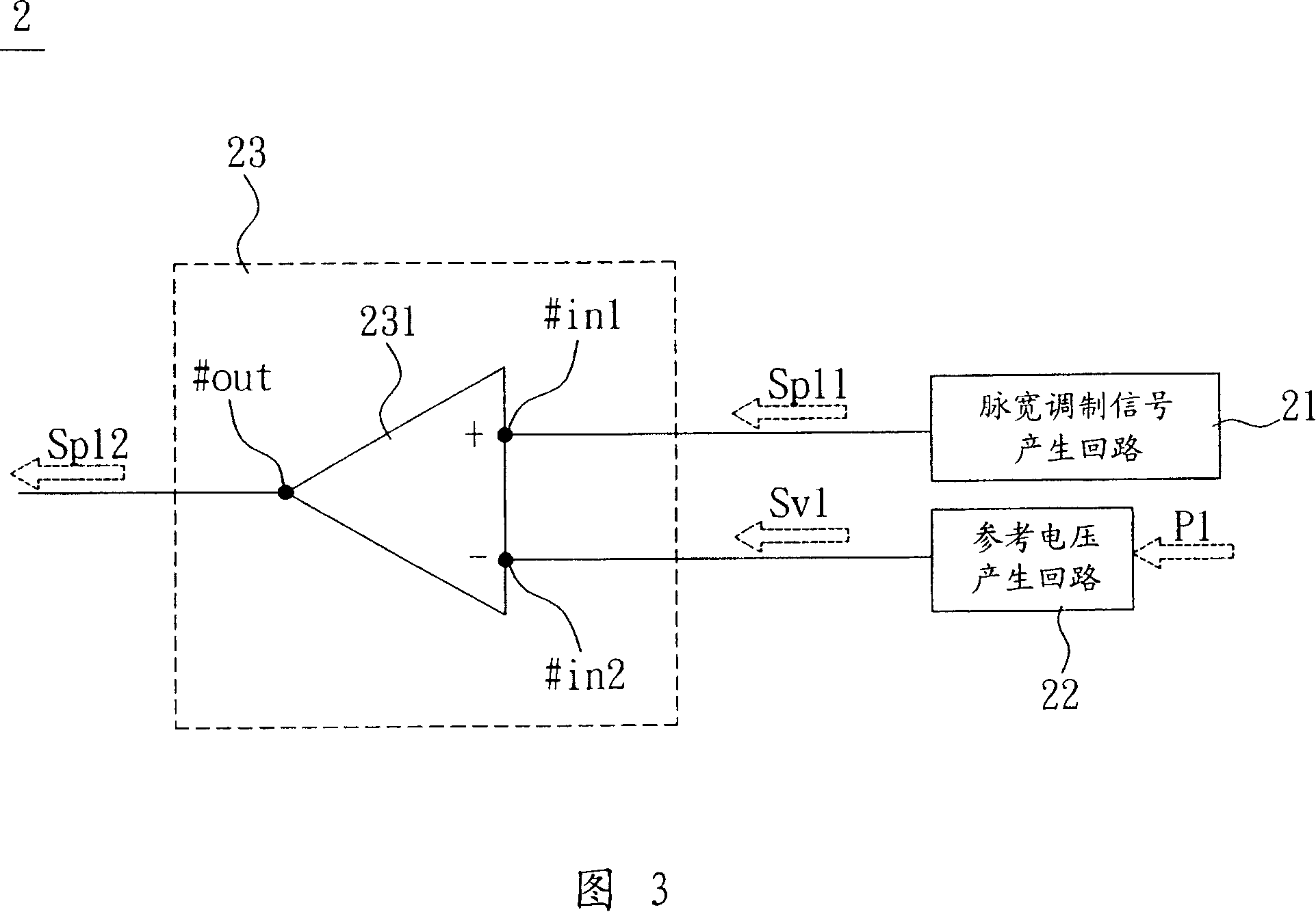
[0042] Referring to FIG. 3 , a level judging device 2 for a PWM signal according to a preferred embodiment of the present invention includes a PWM signal generating circuit 21 , a reference voltage generating circuit 22 and a judging circuit 23 .

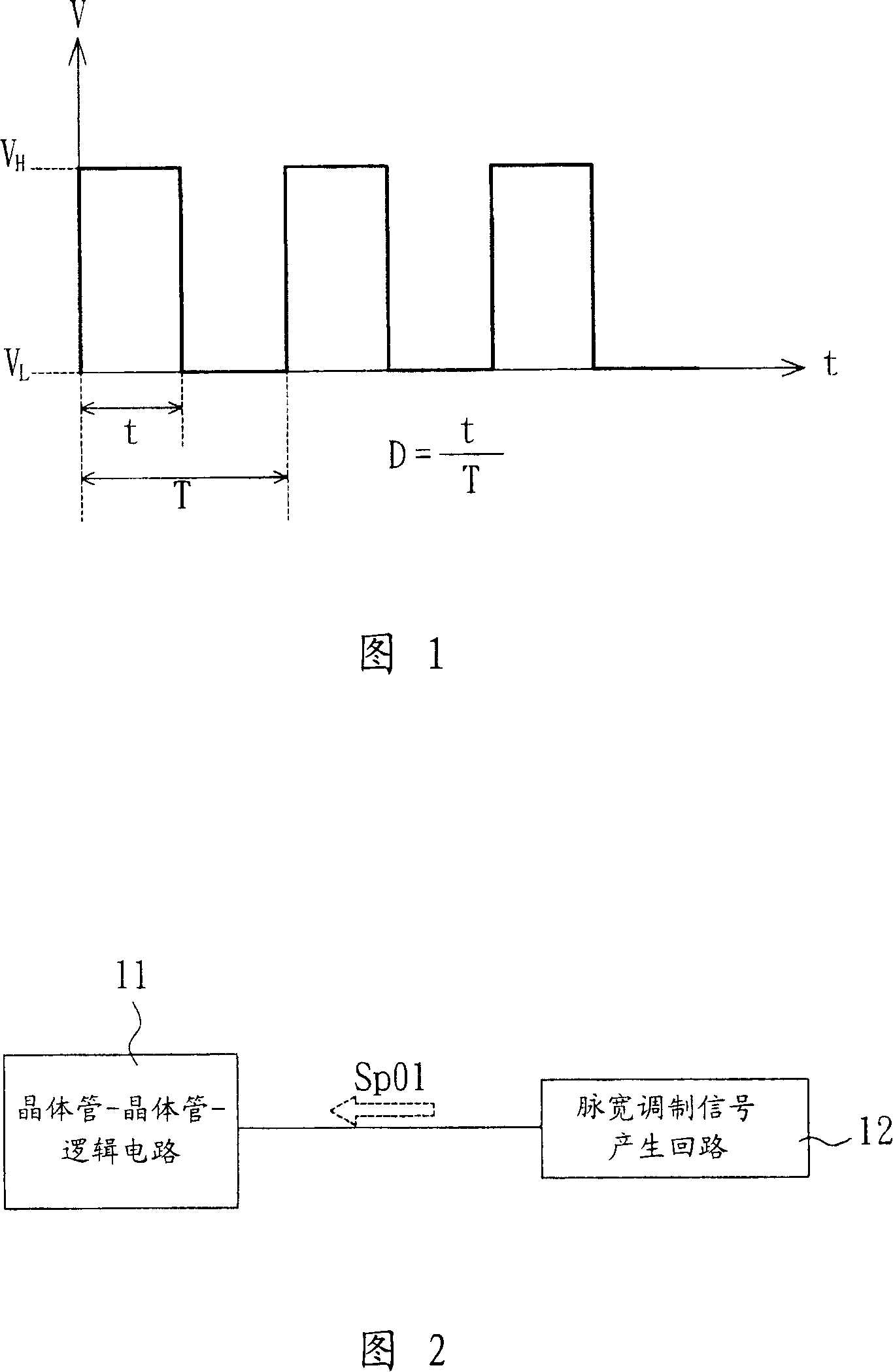
[0043] The PWM signal generating circuit 21 generates the first PWM signal Sp11 , and the frequency, duty cycle and level of the first PWM signal Sp11 can be adjusted arbitrarily according to the requirements of different systems. Moreover, the first PWM signal Sp11 can be generated by an analog circuit or a digital circuit.

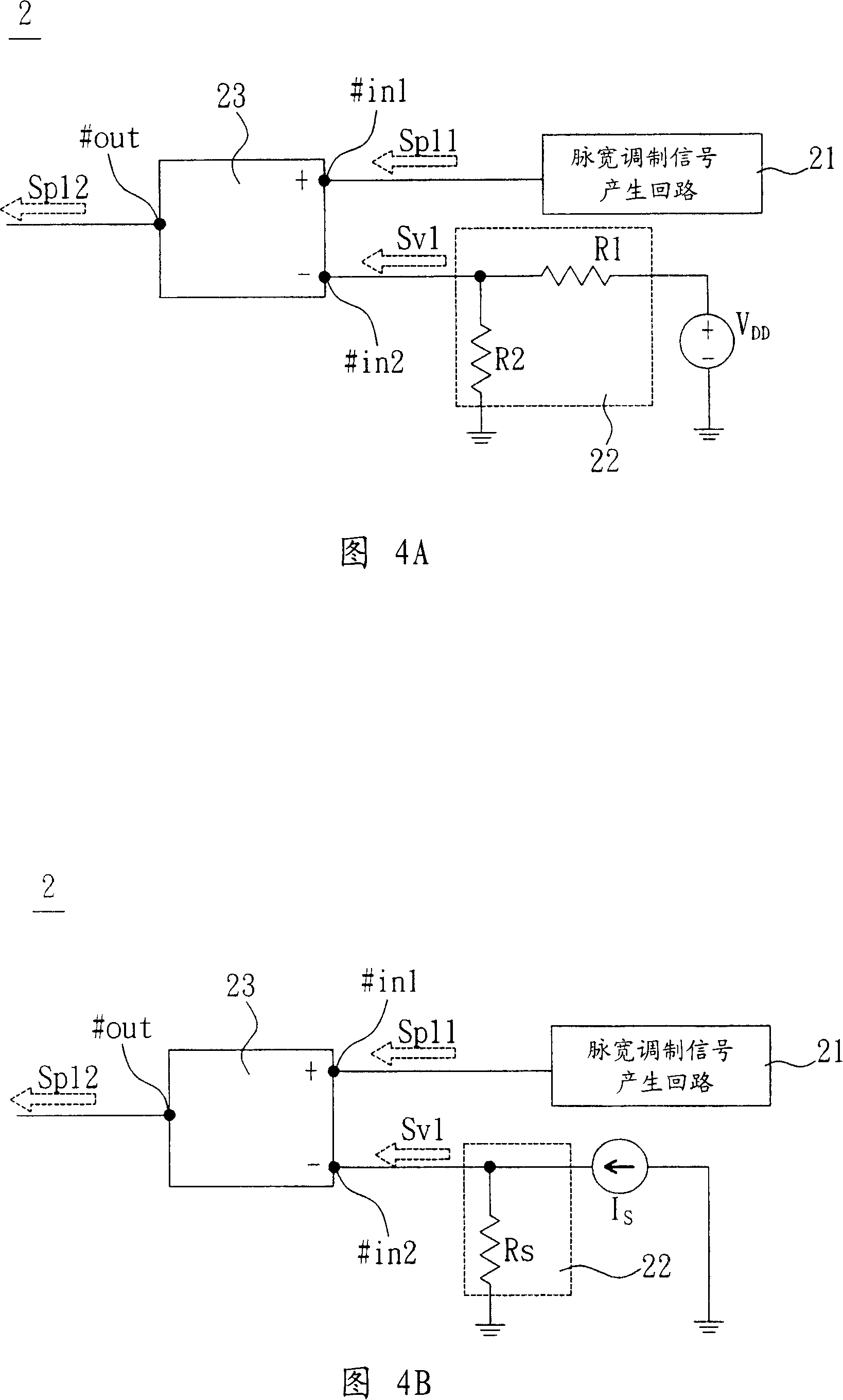
[0044] The reference voltage generating circuit 22 generates a reference voltage signal Sv1 according to the power signal P1. As shown in FIG. 4A, when the power signal P1 is at the voltage VDD, that is, the power signal P1 is gener...


PUM


Abstract

The invention discloses a level deciding device for pulse-width signal and consists of a pulse-width signal generating circuit, a reference voltage reference generating circuit and a deciding circuit. The pulse-width signal generating circuit generates a first pulse-width signal; the reference voltage generating circuit generates a reference voltages signal and the deciding circuit is electrically connected with the pulse-width signal generating circuit and the reference voltages generating circuit and decides the high and low level value of the first pulse width signal according to the reference voltage so as to generate a second pulse-width signal.

Description

technical field [0001] The present invention relates to a judging device and method, in particular to a level judging device and method of a pulse width modulation signal. Background technique [0002] Due to the development of electronic technology, the use of pulse width modulation (Pulse width Modulation, PWM) signals as control signals of electronic components has become more and more popular. [0003] Please refer to FIG. 1 , pulse width modulation is a method of digitally encoding the level of an analog signal, which means converting the analog signal into a square wave with only high and low levels. Its important parameters include high level V H , low level V L And the duty cycle D (Duty Cycle), where the duty cycle D represents the square wave at a high level V H The proportion of the time t in a square wave period T is generally expressed as a percentage. [0004] Please refer to FIG. 2, the known technology is to judge the high and low voltage of the pulse wid...

Claims


Application Information

Patent Timeline
IPC IPC(8): H03K7/08
Inventor 邱进发郭柏村
Owner DELTA ELECTRONICS INC
Why Eureka
Try Eureka