Mixed fluid uniformization device and mixed fluid feeding apparatus

A technology for mixing fluids and supply equipment, which is applied in the field of homogenizing devices for mixed fluids, which can solve the problems that the mixer cannot be fully mixed, and achieve the effect of improving uniformity

Inactive Publication Date: 2008-03-12
KAWASAKI HEAVY IND LTD
View PDF1 Cites 205 Cited by
  • Summary
  • Abstract
  • Description
  • Claims
  • Application Information

AI Technical Summary

Benefits of technology

The technical effect that this technology improves the consistency between different fluids being combined without changing their properties or proportions during processing.

Problems solved by technology

This patented technical problem addressed in this patents relates to improving the quality control of mixture between two materials during manufacturing without causing variations in concentration levels caused by differences in the compositional ratios of components present at the end portions of the feedstock gas passageway.

Method used


Image

  • Mixed fluid uniformization device and mixed fluid feeding apparatus
  • Mixed fluid uniformization device and mixed fluid feeding apparatus
  • Mixed fluid uniformization device and mixed fluid feeding apparatus

Examples


Embodiment Construction

[0089] Next, an embodiment of a mixed fluid homogenizing device and a mixed fluid supply facility including the same according to the present invention will be described with reference to the drawings.

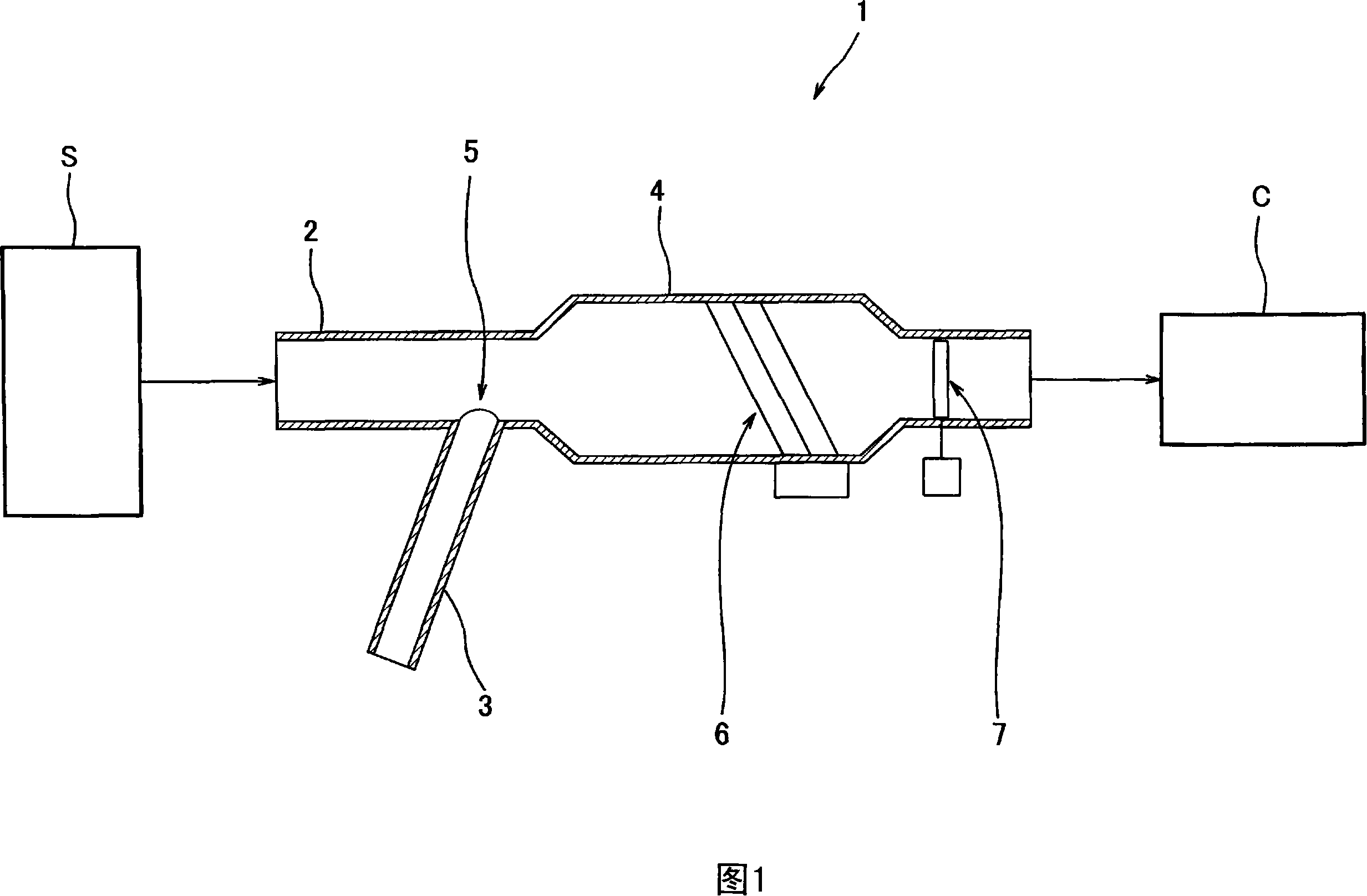
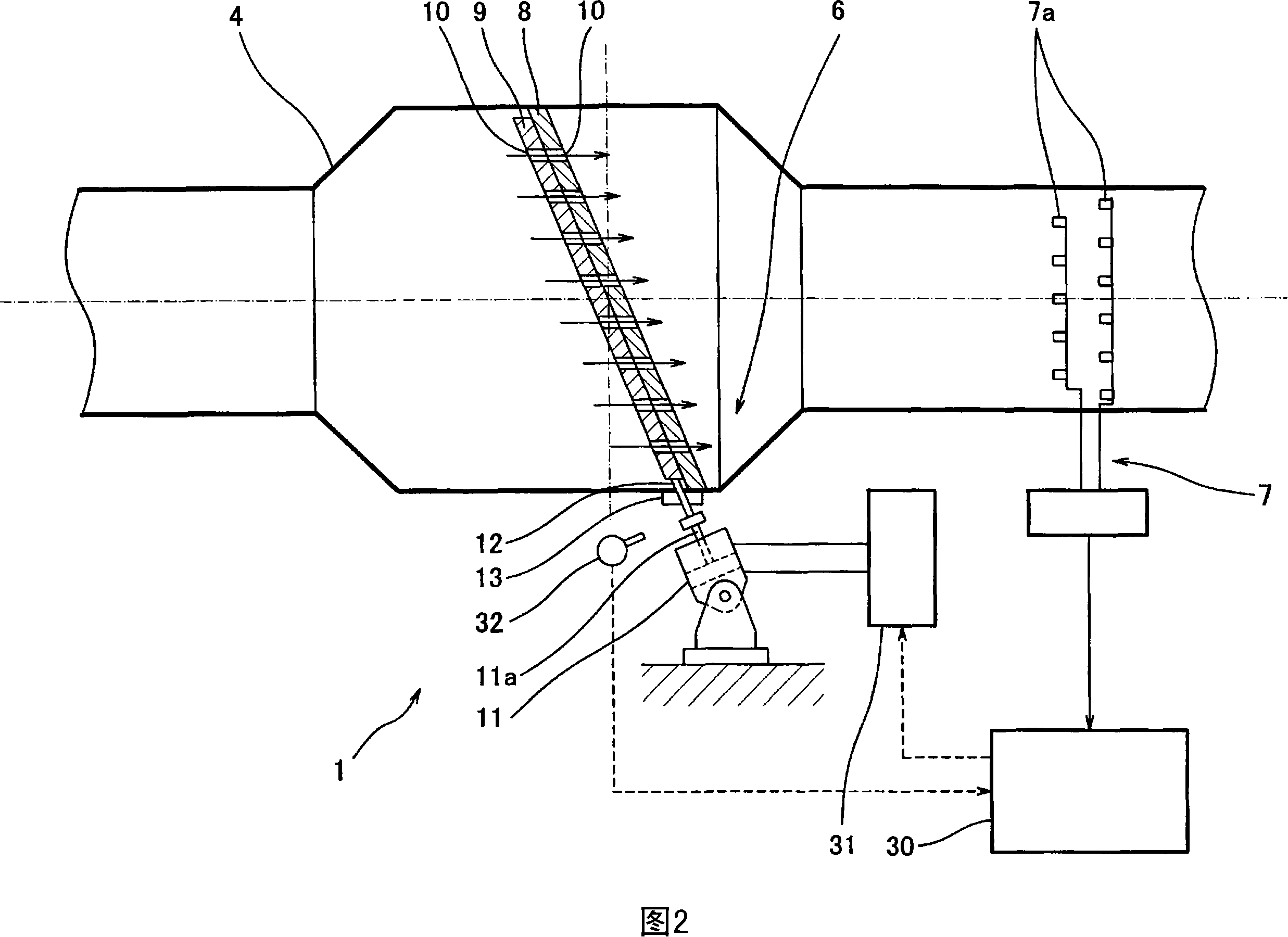
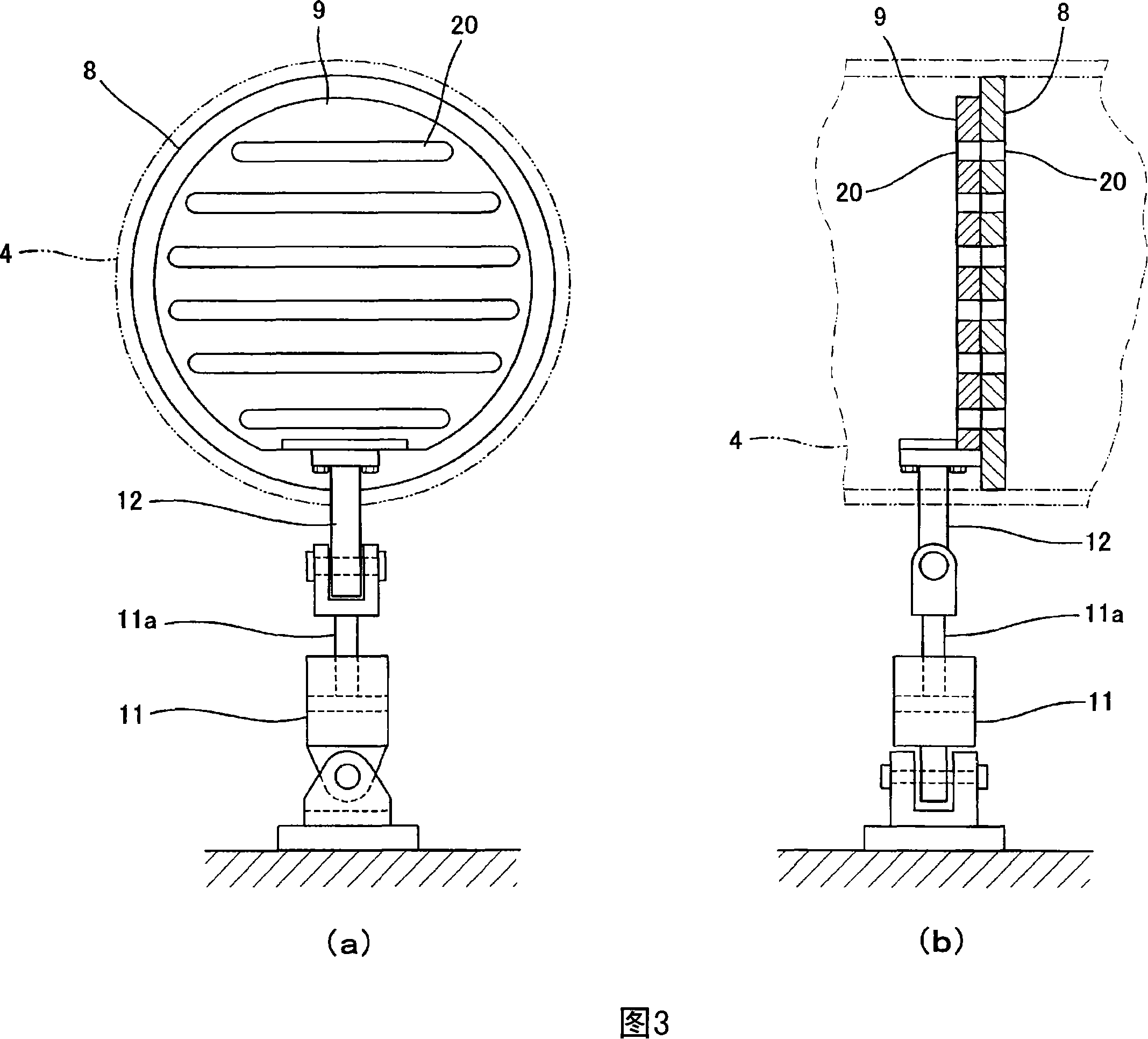
[0090] Fig. 1 is a mixed fluid supply device 1 according to an embodiment of the present invention. As such a supply facility, when using, for example, a by-product gas with fluctuating calorific value generated by a gas supply source S such as a blast furnace or a direct reduction ironmaking facility, as a fuel gas for a gas turbine, there are, for example, various types of by-product gas with different properties. Fuel gas supply equipment supplied after mixing, or fuel gas supply equipment that mixes inert gas as a calorific value reducing gas, or COG as a calorific value increasing gas with these fuel gases. The above-mentioned gas supply source S passes through necessary processing steps including supplying generated gas as fuel, for example, a dust removal step. The flu...


PUM


Abstract

A mixing fluid providing device (1) which provides with the further homogenized mixed state is provided with a mixing gas tubing (4) that mixes the auxiliary gas provided from the main gas tubing and a mixing fluid homogenizing device (6) that is arranged in the mixing gas tubing (4); the mixing fluid homogenizing device (6) is provided with a fixed perforated plate (8) and a movable perforated plate (9) which are mutually overlapped and jointed, and a driving cylinder (11) which causes the movable perforated plate (9) move in the surface direction relative to the fixing perforated plate (9); each perforated plate (8 and 9) is formed with a plurality of through holes (10) and forms a structure which can change the overlapping degree between the through hole (10) of the two perforated plates (9) and the aperture ratio of all through holes (10) by the moving of the movable perforated plate (9).

Description


Claims


Application Information

Patent Timeline
Owner KAWASAKI HEAVY IND LTD
Why Eureka
Try Eureka