Pulling and pushing device for a central buffer coupling of rail vehicles

A traction buffer and coupling technology, which is applied in the direction of traction devices, buffer vehicles, transportation and packaging, etc., can solve the problems of dragging, weakening of stabilizing effect of stabilizing hinges, impact, etc., and achieve the effect of avoiding the acceleration peak

Inactive Publication Date: 2008-03-12
FAIVELEY TRANSPORT REMSCHEID
View PDF2 Cites 24 Cited by
  • Summary
  • Abstract
  • Description
  • Claims
  • Application Information

AI Technical Summary

Problems solved by technology

Here too, when preloaded into the stop on the vehicle side, there is a gap between the hinge shaft and the housing, which causes shocks and dra

Method used


Image

  • Pulling and pushing device for a central buffer coupling of rail vehicles
  • Pulling and pushing device for a central buffer coupling of rail vehicles

Examples


Embodiment Construction

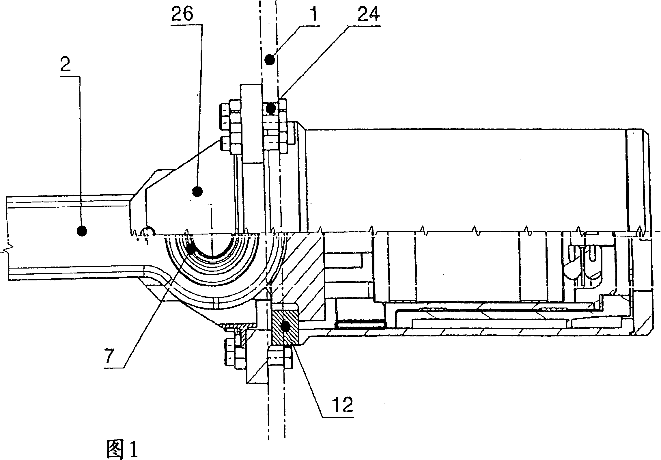
[0019] In FIG. 1, a flanged traction damper with a connecting arm for an intermediate damper coupling of a rail vehicle is shown in a top view in half section. The traction buffer device 100 is screwed to the undercarriage 1 of the rail vehicle via a screw connection part 24 . The connecting arm with the connecting head 2 is articulated on the hinge shaft 4 via the hinge gap spring damper 7 .

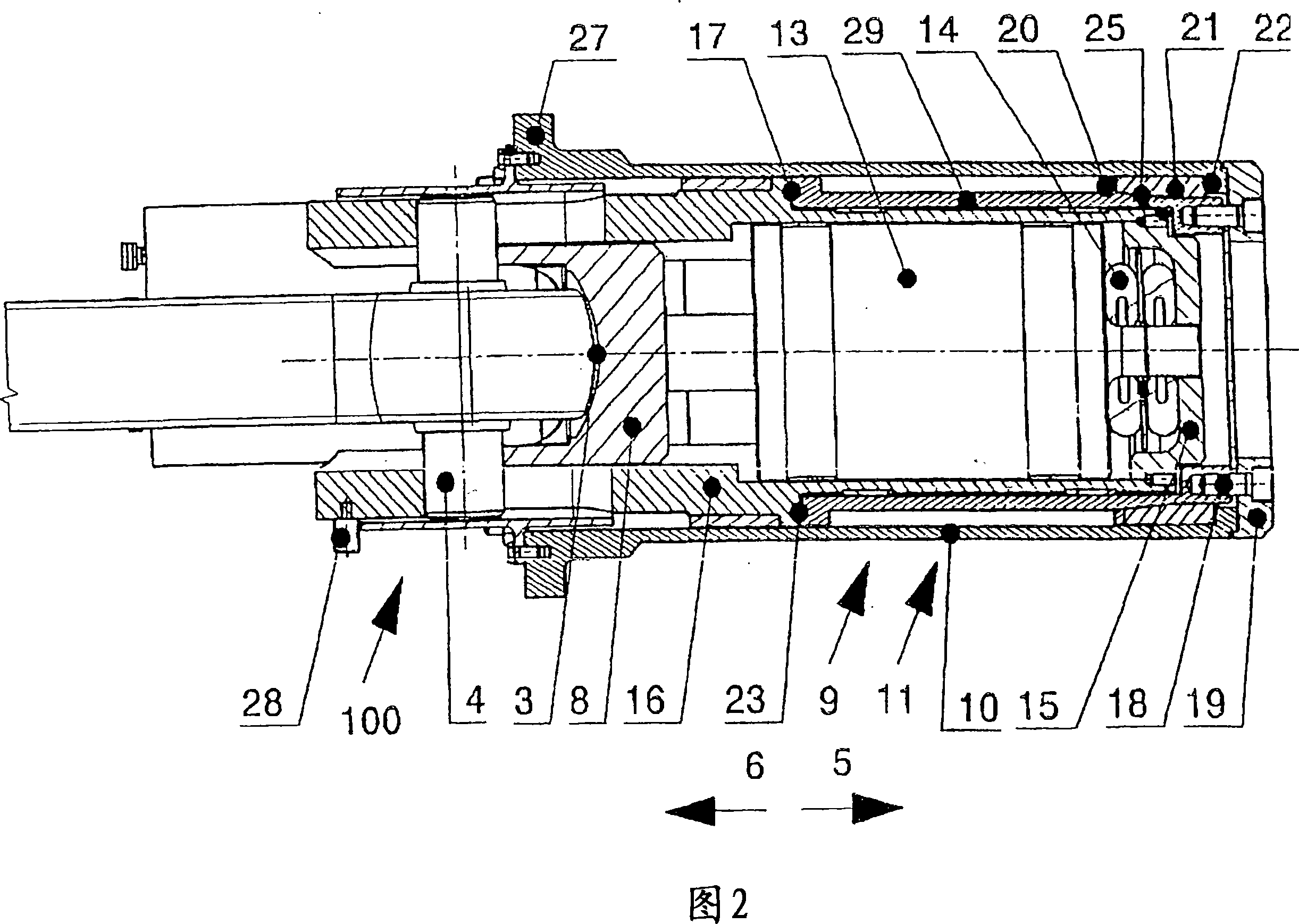
[0020] In FIG. 2 the traction damper is shown in side sectional view. The hinge 3 is supported by the end surface against the pressing plate 8, and the pressing plate transmits the pressing force to the reversible energy consumption system composed of the shock absorber 13 and the unloading spring 14 when the pressing plate is pressed, wherein, through the inner cover plate 15 towards The inner housing 16 provides support. The inner housing 16 is pressed against the deformation element 23 via the stop 17, and the deformation element is supported on the stop 22 of the outer housing 10 ...


PUM


Abstract

The device has a coupling arm with head born elastically pref. via a stabilizer joint. The joint transmits traction and pressure forces into the bogie via an outer housing (10) and energy absorption systems (9,11). The systems are switched in series and are located in the housing. One and/or both systems have an irreversibly deformable deformation element (23), e.g. a mechanical shock absorption part. This is e.g. a tube, which is deformed by a nozzle (25) or a pressure ring (21), after a set pressure and/or traction load limit on shear ring (20) and/or pin has been exceeded. -

Description

technical field [0001] The invention relates to a traction buffer device with a connecting arm, which is used for the intermediate buffer coupling of a rail vehicle. The traction buffer device is fixed on the chassis of the rail vehicle with a flange, and is hinged on a hinge shaft The hinge, especially the stable hinge, elastically supports the connecting arm with the connecting head, and, in the pressing direction, makes the pressing force pass through a pressing plate and a connection without play after exceeding the hinge gap spring damper The prestressed, pressure-side energy dissipation system is supported on the chassis via an outer housing and, in the traction direction, the traction force is passed through the traction stop without play via the hinge shaft and a traction-side energy dissipation system and the outer shell are supported on the chassis. Background technique [0002] Such a device is known, for example, from EP 1 225 114 B1. [0003] According to DE 1...

Claims


Application Information

Patent Timeline
IPC IPC(8): B61G9/04B61G9/22B61D15/06
CPCB61G9/04B61G9/22B61D15/06
Inventor J·本施弗朗茨-彼得·巴特林M·许勒尔A·厄尔德M·朗格
Owner FAIVELEY TRANSPORT REMSCHEID
Why Eureka
Try Eureka