Vacuum cleaner cyclone dust cup with tri-separation function

A separator and vacuum cleaner technology, which is applied to suction filters and other directions, can solve the problem that the separation effect of the vacuum cleaner dust cup is not ideal, and achieve the effect of increasing the separation effect.

Inactive Publication Date: 2008-03-19
NINGBO FUJIA IND
View PDF1 Cites 7 Cited by
  • Summary
  • Abstract
  • Description
  • Claims
  • Application Information

AI Technical Summary

Problems solved by technology

[0003] The technical problem to be solved by the present invention is that the separation effect of the dust cup of the vacuum cleaner with tw

Method used


Image

  • Vacuum cleaner cyclone dust cup with tri-separation function
  • Vacuum cleaner cyclone dust cup with tri-separation function

Examples


Embodiment Construction

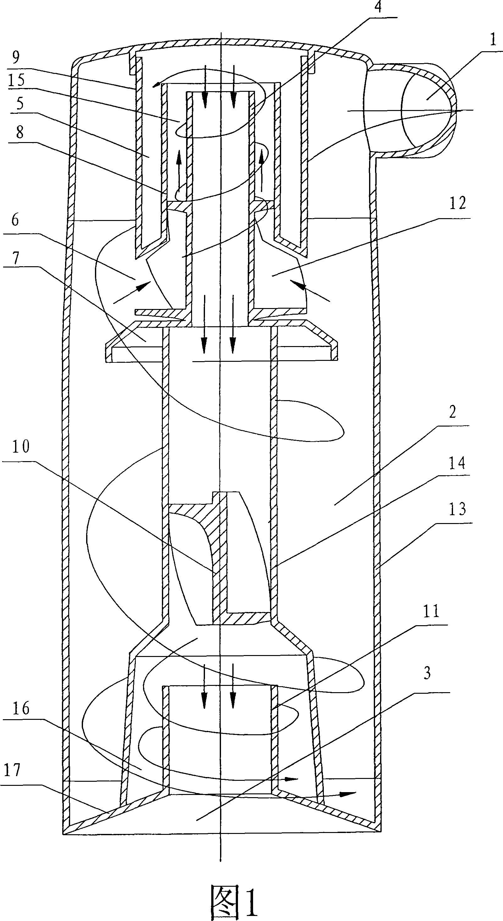
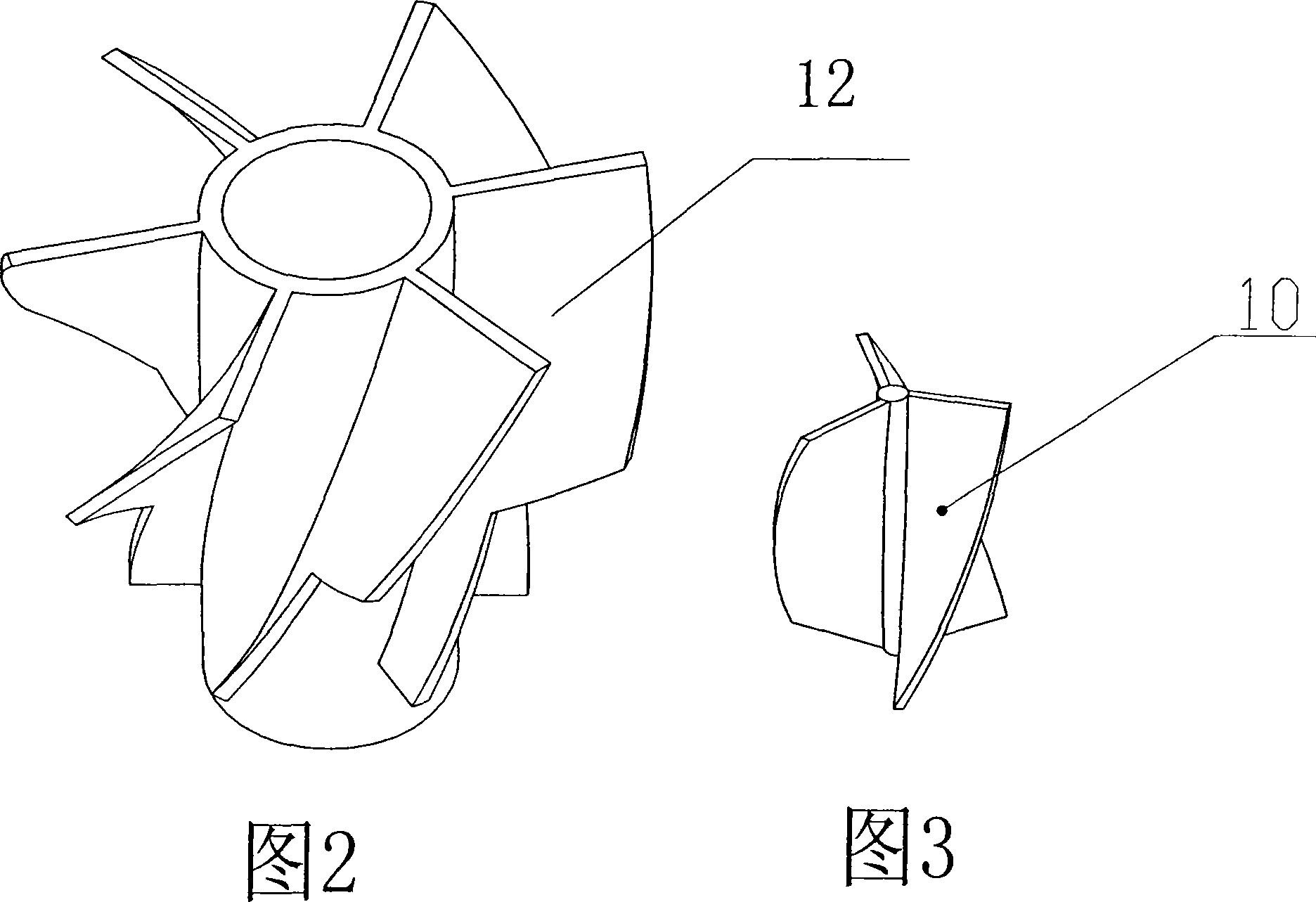
[0009] Shown in Fig. 1 to Fig. 3 is the embodiment of the product of the present invention. As shown in the figure, the dust cup includes a dust cup shell 13, and a dust cup air inlet 1 arranged on the peripheral wall of the dust cup shell 13 tangent to it is placed in a separator in the dust cup, and the separator is provided with an inlet There is a certain drop height between the horizontal position of the top of the air inlet of the separator and the center position of the air inlet of the dust cup. There is an isolation cover 7 under the air inlet 6 of the separator, and the air inlet 6 of the separator is connected to the air inlet 1 of the dust cup. connected. The upper part of the air inlet of the separator is connected with two coaxial inner tubes 8 and outer tubes 9, and the outer wall of the inner tube 8 is closed and connected with the bottom of the inner wall of the outer tube 9, wherein the inner tube 8 communicates with the air outlet 3 arranged at the bottom of...


PUM


Abstract

A vortex type dust cup of a dust collector with the function of thrice separating includes a crust body, an air inlet that is arranged at the crust body and is tangent with the crust body and a separator, which is arranged inside the crust body. Certain fall height is arranged between the level position of the top of the air inlet of the separator and the central position of the dust cup air inlet. The separator is provided with two pieces of an internal pipe and an external pipe, which are coaxially installed. The bottoms of the internal pipe and the external pipe are in close connection. The height of the internal pipe is lower than the height of the external pipe. The air inlet of the separator is an annular body and is formed by the screw-thread-shaped rotary arrangement of screw panels, and the bottom of the separator is fixed at a separating cover. The middle of the internal pipe above a central hole of the separator is connected with a central pipe, which is coaxial with the internal pipe. The central pipe is put through the separating cover and extends downwards to form an extending pipe, which is provided with a small top and a big bottom. A short pipe is arranged inside the lower part of the extending pipe and links the extending pipe, the short pipe and the bottom of the crust body as a dust cup air outlet, which is provided with a trumpet-shaped convex edge. The extending pipe under the separator is provided with a three-vane rotating plate inside. The separation effect towards the air with dust can be further strengthened by thrice separating through the dust cup internal cavity.

Description

technical field [0001] The invention relates to the technical field of vacuum cleaner manufacturing, in particular to a separation device for air and dust of a centrifugal vacuum cleaner. Background technique [0002] The application number I have applied for is "200510049880.2", "Integral double-separated vacuum cleaner dust cup". Compared with the prior art, although the effect of separating air and dust has been greatly improved, there is still a small amount of fine dust that has not been separated. The air flow is adsorbed on the filter of the vacuum cleaner. After repeated use, a lot of dust still accumulates on the filter, which blocks the circulation of the air over time. Therefore, it is necessary to produce a separator with better separation effect on the original basis. . Contents of the invention [0003] The technical problem to be solved by the present invention is that the separation effect of the dust cup of the vacuum cleaner with two separation functions...

Claims


Application Information

Patent Timeline
IPC IPC(8): A47L9/16
Inventor 郎维国
Owner NINGBO FUJIA IND
Why Eureka
Try Eureka