

Oil-water separating tower
A technology of oil-water separation and tower section, which is applied in the field of oil-water separation tower and oil-water separation process. It can solve the problems of easy plugging of fillers, short liquid residence time, secondary pollution, etc., to increase residence time, increase separation effect, and improve mutual contact. Effect
- Summary
- Abstract
- Description
- Claims
- Application Information
AI Technical Summary
Problems solved by technology
Method used
Image

Examples
Embodiment 1
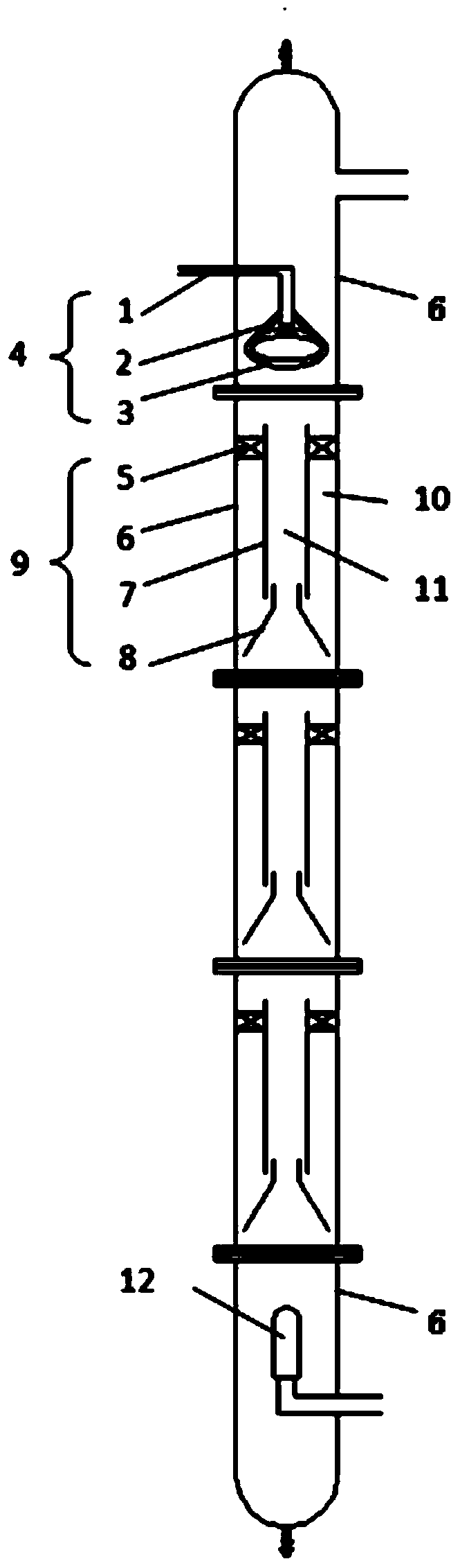
[0027] Example 1: Use the above-mentioned experimental equipment to separate oil and water from industrial waste liquid. The process is as follows: fill the device with industrial waste liquid at normal temperature and pressure, then introduce microbubble gas into the device, adjust the two-phase flow rate to be stable, and carry out Continuous and stable operation. The operating industrial waste liquid flow rate is 1t / h, the main component is the emulsion of organic oil phase and water, of which the oil phase content is 70%; the gas flow rate is 20m 3 / h. By adopting the oil-water separation tower of the present invention, the yield of oil is 97%, which is 25% higher than that of other processes.
Embodiment 2
[0028] Example 2: Use the above-mentioned experimental equipment to separate oil and water from industrial waste liquid. The process is as follows: fill the device with industrial waste liquid at normal temperature and pressure, then introduce microbubble gas into the device, adjust the two-phase flow rate to be stable, and carry out Continuous and stable operation. The flow rate of industrial waste liquid is 2t / h, the main component is the emulsion of organic oil phase and water, of which the oil phase content is 60%; the gas flow rate is 25m 3 / h. By adopting the oil-water separation tower of the present invention, the yield of oil is 97%, which is 25% higher than that of other processes.
PUM
| Property | Measurement | Unit |
|---|---|---|
| Diameter | aaaaa | aaaaa |
| Height | aaaaa | aaaaa |
Abstract
Description
Claims
Application Information