
Hyperbolic filler bending mold

A hyperbolic turning and mold technology, applied in the direction of forming tools, manufacturing tools, metal processing equipment, etc., can solve the problems of affecting separation efficiency, affecting separation effect, and reducing production efficiency, so as to improve separation efficiency, improve separation effect, reduce The effect of production costs

Inactive Publication Date: 2016-04-06
TIANJIN NORTH EFFICIENT PETROCHEM EQUIP MFG CO LTD
View PDF6 Cites 2 Cited by
  • Summary
  • Abstract
  • Description
  • Claims
  • Application Information

AI Technical Summary

Problems solved by technology

[0003] At present, most of the existing wire mesh packings are punched into straight grains when they are punched and bent. When this kind of straight grained wire mesh packings are used, the effect is not good, and the liquid above the wire mesh packings flows to the tower. When the outer edge of the wire mesh packing on the side of the wall is straight, the liquid will flow out along the outer edge of the wire mesh packing, which affects the separation effect. At the same time, when the hot gas above the tower When flowing to the wire mesh packing below, the liquid above the straight-grained wire mesh packing will splash, and convection will occur in the tower, which further affects the separation efficiency, reduces the production efficiency, and increases the production cost of the enterprise
[0004] Through searching, no patent publications related to this patent application have been found

Method used


Image

  • Hyperbolic filler bending mold
  • Hyperbolic filler bending mold
  • Hyperbolic filler bending mold

Examples


Embodiment Construction

[0024] In order to further understand the content, characteristics and effects of the present invention, the following examples are given, and detailed descriptions are given below with reference to the accompanying drawings. It should be noted that this embodiment is descriptive, not restrictive, and cannot thereby limit the protection scope of the present invention.

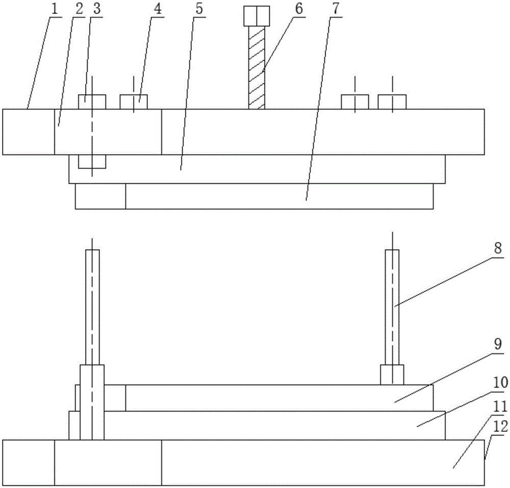
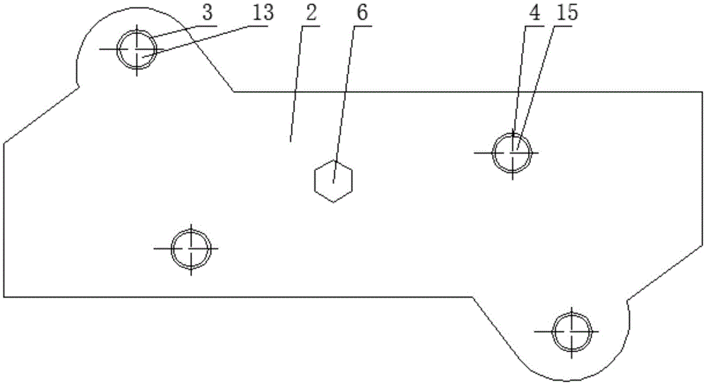
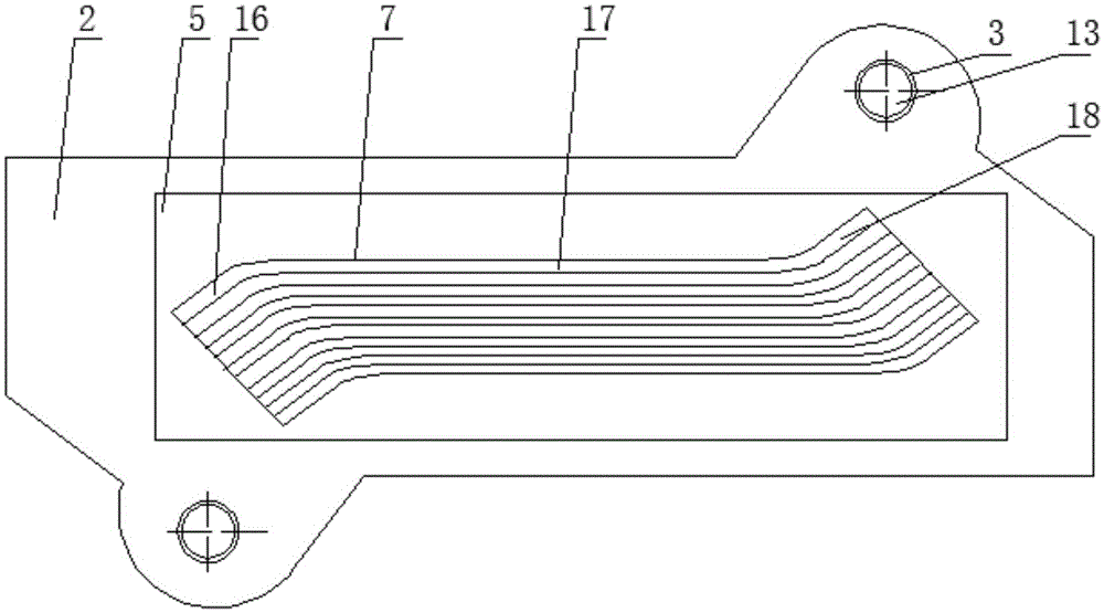
[0025] A hyperbolic packing bending die, such as figure 1 and figure 2 As shown, the mold includes an upper die 1 connected to the punch and a lower die 12 detachably arranged on the working platform of the punch press, and the upper die and the lower die are vertically oppositely arranged during use;

[0026] The upper mold includes a punch connecting part 2, an upper connecting plate 5 and an upper die pressing plate 7 which are connected in sequence, and the punch connecting part is fixed on the top surface of the upper connecting plate in parallel, and the upper connecting plate The upper molded plate is...


PUM


Abstract

The invention relates to a hyperbolic filler bending mold. The mold comprises an upper die and a lower die, wherein the upper die is connected with a punching head; the lower die is detachably arranged on a worktable of a punch press; the upper die and the lower die are arranged oppositely along the vertical direction in use; the upper die comprises a punching head connecting part, an upper connecting plate and an upper die pressing plate which are sequentially connected in arrangement; the lower die comprises a base, a lower connecting plate and a lower die pressing plate which are sequentially connected in arrangement. According to the mold, the outer edge of metal gauze filler is bent, so liquid cannot flow out along the outer edge of the metal gauze filler, a good using effect is achieved, and the separation effect is improved; meanwhile, when hot air in the upper part inside a tower flows towards the metal gauze filler at the lower part, sputtering of the liquid above the metal gauze filler which has a hyperbolic structure is prevented, and no convection is generated inside the tower, so the separation efficiency is further improved, the production efficiency is improved, and the production cost of an enterprise is lowered.

Description

technical field [0001] The invention belongs to the technical field of filler manufacturing equipment, in particular to a hyperbolic filler bending die. Background technique [0002] Wire mesh packing is currently the main chemical packing used in the fields of fine chemicals, biomedicine, and ecological environmental protection. Its production method is to emboss and bend strip-shaped raw materials into discs or other arbitrary geometric shapes. Metal mesh packing has the characteristics of small resistance, uniform distribution of gas and liquid, high separation efficiency, large flux, and no obvious amplification effect. It is used in negative pressure, normal pressure and pressurized operations, especially for precision distillation and vacuum distillation devices. It provides an effective means for the rectification of difficult-to-separate and heat-sensitive substances. The wire mesh filler increases the uniform distribution of the liquid and the wetting performance o...

Claims


Application Information

Patent Timeline
IPC IPC(8): B21D37/10B21D37/12B21D11/10
CPCB21D11/10B21D37/10B21D37/12
Inventor 李富玉
Owner TIANJIN NORTH EFFICIENT PETROCHEM EQUIP MFG CO LTD
Learn More