Electrophoresis coating method and whole set apparatus for pattern transfer of positive electrophoresis coating on printing board

An electrophoretic coating, electrophoretic coating technology, applied in the direction of electrolytic coating, electrophoretic plating, application of photosensitive materials, etc., can solve the problem that no solution is found, the graphic lines cannot meet the requirements of small and clear, and achieve fine circuit graphics. Effect

Inactive Publication Date: 2011-04-06
武汉科利尔立胜工业研究院有限公司
View PDF0 Cites 1 Cited by
  • Summary
  • Abstract
  • Description
  • Claims
  • Application Information

AI Technical Summary

Problems solved by technology

The existing printed circuit board industry generally uses conventional dry film treatment methods and liquid brushing methods to transfer circuit graphics. This method is more suitable for larger printed circuit boards. Small and exquisite, developing in a more subtle direction, the graphic lines produced by the conventional line graphic production method in the prior art can no longer meet the requirements of small and clear
In order to solve the above problems, those skilled in the art have been doing a lot of research, but have not found a solution to the problem

Method used


Image

  • Electrophoresis coating method and whole set apparatus for pattern transfer of positive electrophoresis coating on printing board
  • Electrophoresis coating method and whole set apparatus for pattern transfer of positive electrophoresis coating on printing board
  • Electrophoresis coating method and whole set apparatus for pattern transfer of positive electrophoresis coating on printing board

Examples


Embodiment 1

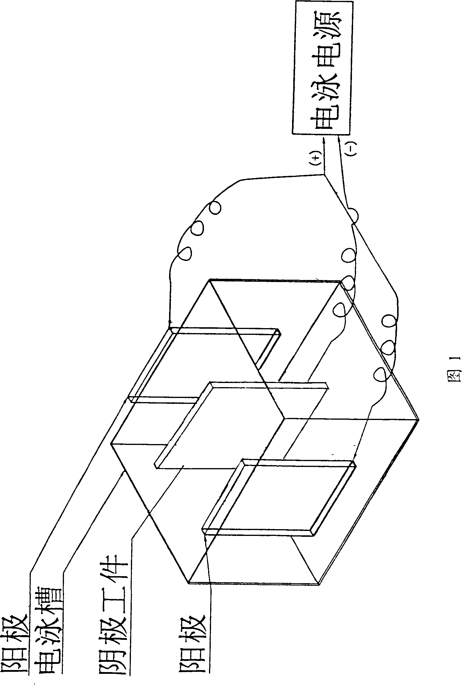
[0027] As shown in Figure 1, the present invention adopts cathodic electrophoresis process, specifically comprises the following steps:

[0028] (1) Connect the printed circuit board and the conductive device as the cathode, the conductive device is connected to the negative pole of the electrophoresis power supply, and the anode of the electrophoresis device is connected to the positive pole of the power supply as the anode system;

[0029] (2) Place the printed circuit board in an electrophoresis tank filled with an electrophoretic paint solution for electrophoresis.

[0030] (3) After electrophoresis, rinse off the floating paint on the surface of the printed circuit board;

[0031] (4) The printed circuit board is photosensitively treated by photocuring equipment, so that the electrophoretic paint film is leveled and formed;

[0032] (5) The electrophoretic positive electrophoretic paint film is processed to produce printed board graphics through exposure, development and...

Embodiment 2

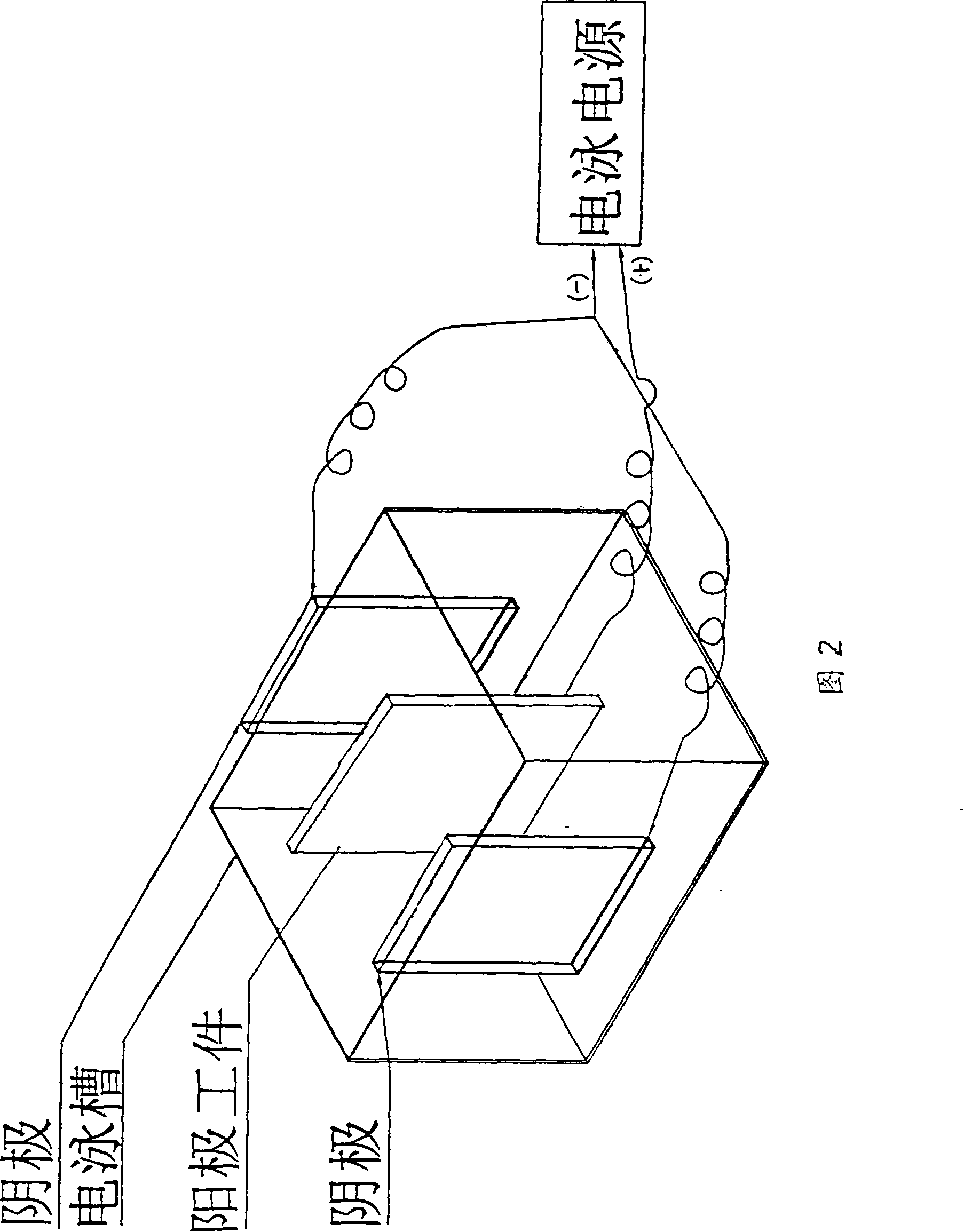
[0039] As shown in Figure 2, the present invention also can adopt anodic electrophoresis process, specifically comprises the following steps:

[0040] (1) Connect the printed circuit board and the conductive device as the anode system, the conductive device is connected to the positive pole of the electrophoresis power supply, and the cathode of the electrophoresis device is connected to the negative pole of the power supply as the cathode system;

[0041] Other steps and the equipment used are the same as in Example 1.

[0042] In the above two embodiments, the printed circuit board is a single-layer, double-layer or multi-layer printed circuit board; wherein the electrophoretic coating used in the electrophoresis process includes polybutadiene resin, phenolic resin, epoxy resin , acrylic or polyurethane resin; wherein the electrophoretic coating used in the electrophoretic process includes colorless transparent, matte colorless or colored coatings; wherein the electrophoreti...


PUM


Abstract

The present invention relates to a positive electrophoresis coating method and a complete set of equipment when a positive electrophoresis coating is used in image transferring of printed boards; the present invention adopts anode and cathode electrophoresis processes, and comprises the concrete steps as follow: (1) an anode or a cathode system can be achieved by connecting a printed board and a conductive device; the conductive device is connected with the anode or cathode of the electrophoresis power; the anode or cathode of the conductive device is connected with the anode or cathode of power to achieve a anode or a cathode system; (2) the printed board is positioned in the electrophoretic tank filled with electrophoretic painting solution to be conducted electrophoresis; (3) having treated by posing, developing and etching, the positive electrophoretic coating film of the electrophoresis can be made out an image of the printed board. The present invention solves the problem further refining the lines in image transferring of the printed circuit board, as well as making the image of the printed circuit board more sophisticated, more accurate, more compact, and thereby electronic products can meet the miniaturized requirement.

Description

technical field [0001] The invention relates to a technical method and a complete set of equipment for applying electrophoretic paint to printed boards, in particular to an electrophoretic coating method and complete set of equipment for pattern transfer of positive electrophoretic paint on printed boards. Background technique [0002] Since the development and industrial application of electrophoretic coating technology in the 1960s, it has excellent high corrosion resistance, water-based environmental protection, high penetration rate, high Coulomb efficiency, insoluble coating, stable bath solution, and automation High, continuous production and other advantages, it has been widely used in the automotive industry, motorcycle industry, household appliances, instrumentation, military building materials, decorative hair accessories, glasses locks, hardware light industry, daily necessities and other industries, and has gradually replaced the conventional surface Coating tech...

Claims


Application Information

Patent Timeline
Patent Type & Authority Patents(China)
IPC IPC(8): G03C1/74C25D13/06
Inventor 李再亮
Owner 武汉科利尔立胜工业研究院有限公司
Why Eureka
Try Eureka